Waste water heat exchange device and operation method thereof

A technology of heat exchange device and waste water, which is applied in the direction of solar thermal energy, solar thermal power generation, solar collectors, etc., and can solve problems such as the decline in the heat collection efficiency of the plate surface temperature of solar collectors and the inability to realize 24h continuous heating.

Active Publication Date: 2021-05-14
北京道荣新兴能源有限公司 +1
View PDF6 Cites 0 Cited by
  • Summary
  • Abstract
  • Description
  • Claims
  • Application Information

AI Technical Summary

Problems solved by technology

[0004] The purpose of the present invention is to provide a waste water heat exchange device and its operation method, which solves the problem that the increase of the surface temperature of the solar collecto...

Method used


Image

  • Waste water heat exchange device and operation method thereof
  • Waste water heat exchange device and operation method thereof
  • Waste water heat exchange device and operation method thereof

Examples


Embodiment Construction

[0041] The following will clearly and completely describe the technical solutions in the embodiments of the present invention with reference to the accompanying drawings in the embodiments of the present invention. Obviously, the described embodiments are only some, not all, embodiments of the present invention. Based on the embodiments of the present invention, all other embodiments obtained by persons of ordinary skill in the art without making creative efforts belong to the protection scope of the present invention.

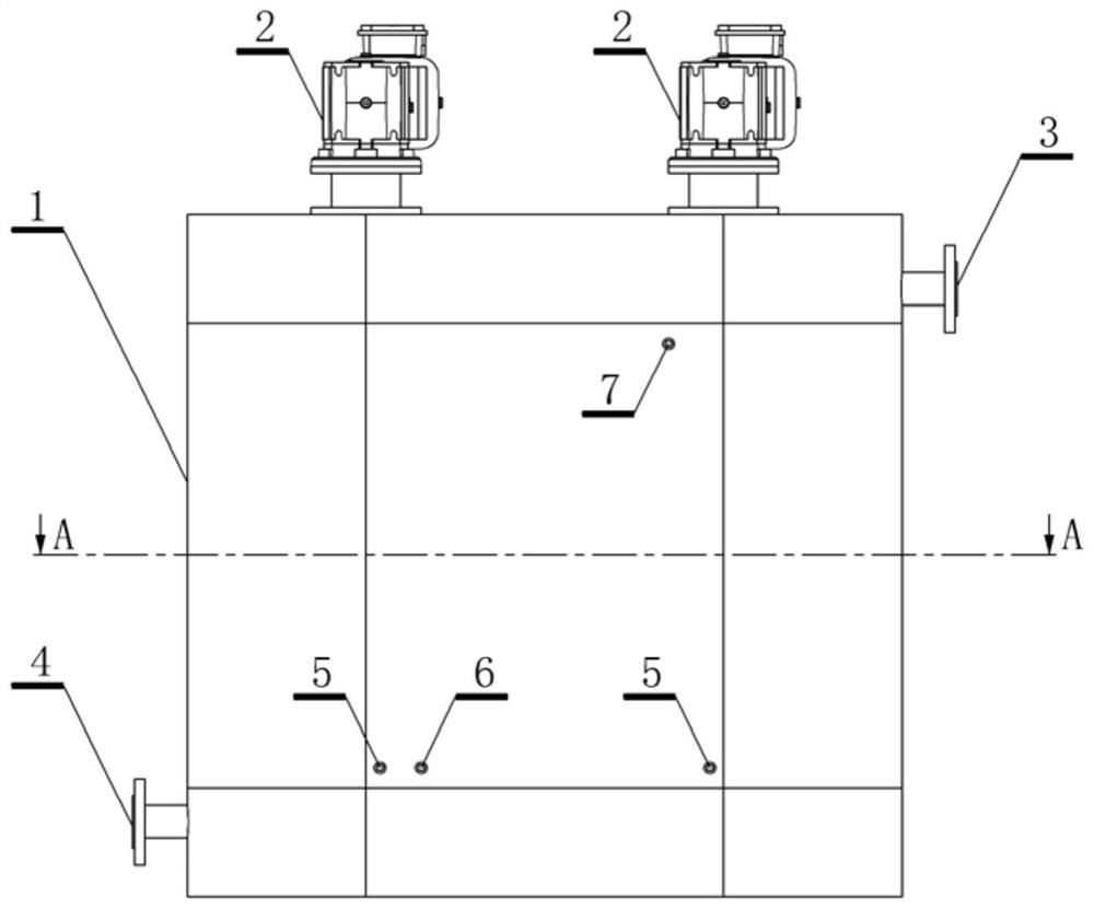
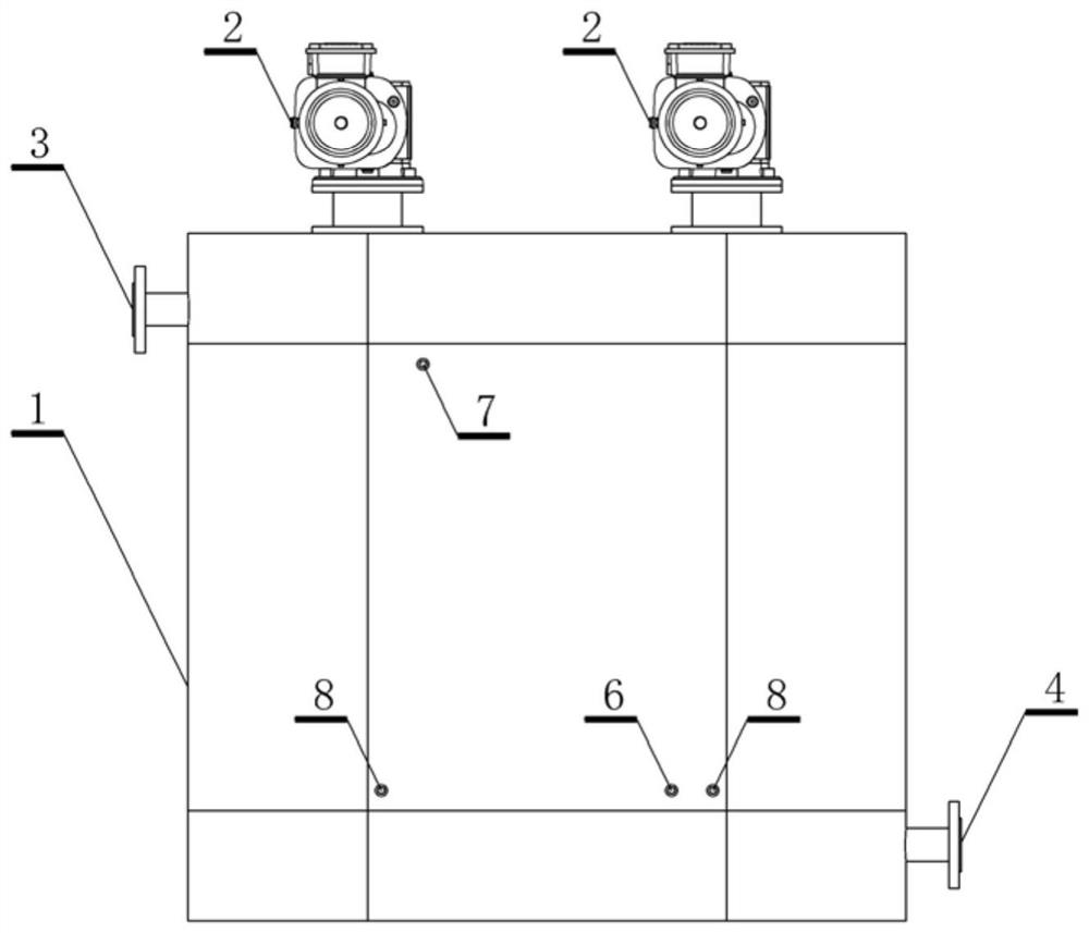
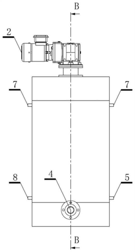
[0042] Such as figure 1 , figure 2 , image 3 , Figure 4 , Figure 5 , Figure 6 , Figure 7 , Figure 8 , Figure 9 , Figure 10 , Figure 11 As shown, a waste water heat exchange device provided by the present invention consists of a housing 1, a geared motor 2, a waste water inlet 3, a waste water outlet 4, a working medium inlet 5, a solar energy inlet 6, a solar energy outlet 7, and a working medium outlet 8 , separation surface 9, stirring de...


PUM


Abstract

The invention provides a waste water heat exchange device and an operation method thereof. A shell is provided with an outer wall plate and an inner wall plate, and a waste water space surrounded by the inner wall plate communicates with a waste water inlet and a waste water outlet; an annular interlayer space is formed between the outer wall plate and the inner wall plate and is divided into a working medium heat exchange channel and a solar heat exchange channel; the working medium heat exchange channel communicates with a working medium inlet and a working medium outlet so that a working medium can enter and exit; the solar heat exchange channel communicates with a solar inlet and a solar outlet so that a solar heat exchange medium can enter and exit; and a stirring deicer is also arranged in the waste water space, is connected with a power device and can stir in the wastewater space. The waste water heat exchange device can also be combined with a solar heating system and a heat pump system to supply heat to a tail end system in a combined mode.

Description

technical field [0001] The invention relates to a heat exchange device. The device and its system can maximize the use of solar energy and waste heat in waste water in winter to heat buildings directly or through a heat pump system. Background technique [0002] With the substantial growth of world energy consumption, people shift the focus of energy utilization to the development and utilization of renewable energy. Solar energy has attracted people's attention for its inexhaustible, cheap, safe, non-transportable, clean and pollution-free features. Solar energy utilization technologies such as photothermal, photoelectric, and photochemical have developed rapidly. [0003] With the improvement of living standards, heat users have higher and higher requirements for heating. Since solar energy is greatly affected by seasons and weather, and the heat flux density is low, various forms of direct solar heat utilization systems are subject to certain restrictions in application. ...

Claims


Application Information

Patent Timeline
IPC IPC(8): F24S10/30F24S40/40F24S40/70F24S50/40F24S80/30
CPCF24S10/30F24S50/40F24S40/70F24S40/40F24S80/30Y02E10/44
Inventor 薛道荣韩成明杨胜东庞爱红
Owner 北京道荣新兴能源有限公司
Why Eureka
Try Eureka