
Wafer thickness laser full-automatic testing machine

A fully automatic testing and wafer thickness technology, applied in measurement devices, optical devices, instruments, etc., can solve the problems of low measurement accuracy and inconvenient wafer fixation, achieve accurate detection, avoid manual contact, and prevent losses Effect

Pending Publication Date: 2021-05-14
北京三禾泰达技术有限公司
View PDF0 Cites 0 Cited by
  • Summary
  • Abstract
  • Description
  • Claims
  • Application Information

AI Technical Summary

Problems solved by technology

[0005] The technical problem to be solved by the present invention is to overcome the existing defects and provide a laser automatic wafer thickness testing machine to solve the problems of low measurement accuracy and inconvenient fixing of the wafer proposed in the above background technology

Method used


Image

  • Wafer thickness laser full-automatic testing machine
  • Wafer thickness laser full-automatic testing machine
  • Wafer thickness laser full-automatic testing machine

Examples


Embodiment Construction

[0032] The following will clearly and completely describe the technical solutions in the embodiments of the present invention with reference to the accompanying drawings in the embodiments of the present invention. Obviously, the described embodiments are only some, not all, embodiments of the present invention. Based on the embodiments of the present invention, all other embodiments obtained by persons of ordinary skill in the art without making creative efforts belong to the protection scope of the present invention.

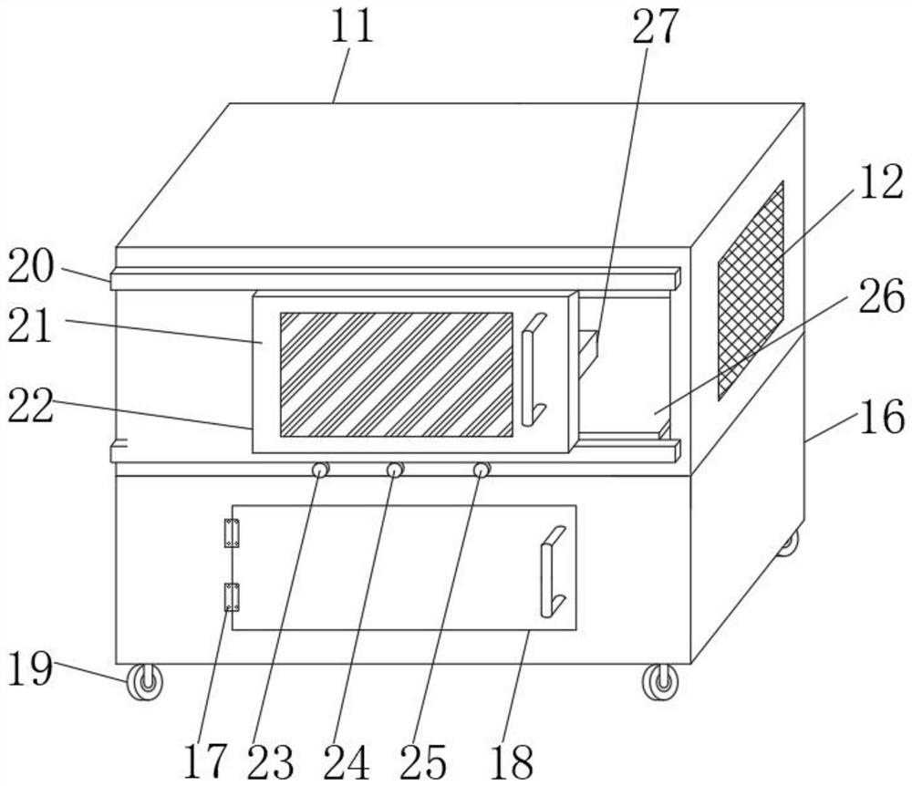
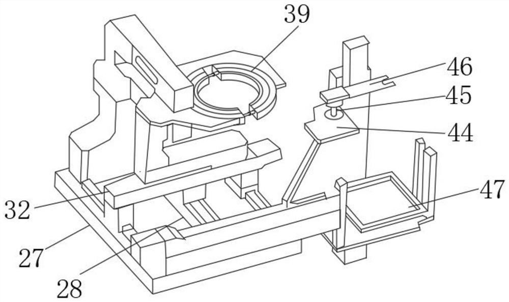
[0033] see Figure 1-8, the present invention provides a technical solution: a fully automatic laser testing machine for wafer thickness, including a machine power-on module 1, an upper outer box 11, a lower outer box 16 and a high-precision platform 27, and the upper outer box 11 is fixedly connected to the lower outer box. The upper end of the box 16 and the inner bottom of the upper outer box 11 are provided with a workbench 26, and the surface of the workb...


PUM


Abstract

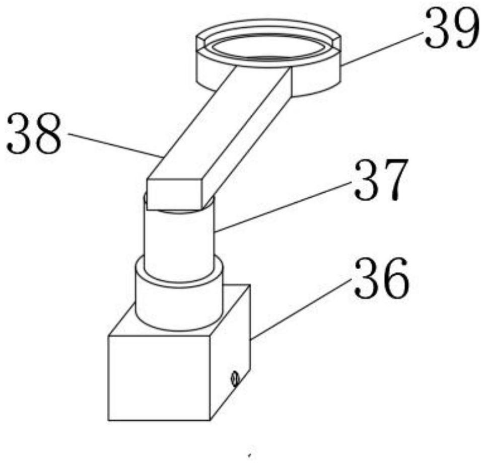
The invention discloses a wafer thickness laser full-automatic testing machine. The wafer thickness laser full-automatic testing machine comprises a machine power-on module, an upper outer box, a lower outer box and a high-precision platform; the upper outer box is fixedly connected to the upper end of the lower outer box; a workbench is arranged at the bottom end in the upper outer box; the surface of the workbench is provided with the high-precision platform and a laser emitter; a Y-axis moving block is arranged at the upper end of the surface of the high-precision platform; an X-axis moving block is arranged on the upper surface of the Y-axis moving block; the upper surface of the X-axis moving block is slidably connected with a sliding block; the upper end of the sliding block is fixedly connected with a first hydraulic cylinder; the upper surface of the first hydraulic cylinder is fixedly connected with a connecting rod; and one end, far away from the first hydraulic cylinder, of the connecting rod is provided with outer fixing rings. According to the wafer thickness laser full-automatic testing machine of the invention, the outer fixing rings and an inner fixing rings are arranged, a hydraulic rod is arranged between the two outer fixing rings, and a wafer between the two inner fixing rings can be conveniently fixed through the extension or shortening of the hydraulic rod.

Description

technical field [0001] The invention belongs to the technical field of wafer thickness testing, and in particular relates to a laser automatic testing machine for wafer thickness. Background technique [0002] Wafer refers to the silicon wafer used to make silicon semiconductor circuits, and its raw material is silicon. High-purity polycrystalline silicon is dissolved and mixed with silicon crystal seeds, and then slowly pulled out to form cylindrical single crystal silicon. After the silicon ingot is ground, polished, and sliced, it forms a silicon wafer, that is, a wafer. At present, domestic wafer production lines are mainly 8-inch and 12-inch. [0003] The main processing methods of wafers are sheet processing and batch processing, that is, one or more wafers are processed at the same time. As semiconductor feature sizes become smaller and processing and measurement equipment become more advanced, new data characteristics emerge in wafer processing. At the same time,...

Claims


Application Information

Patent Timeline
Patent Type & Authority Applications(China)
IPC IPC(8): G01B11/06
CPCG01B11/06
Inventor 贾怀宇
Owner 北京三禾泰达技术有限公司
Learn More