
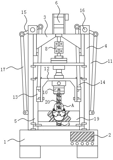
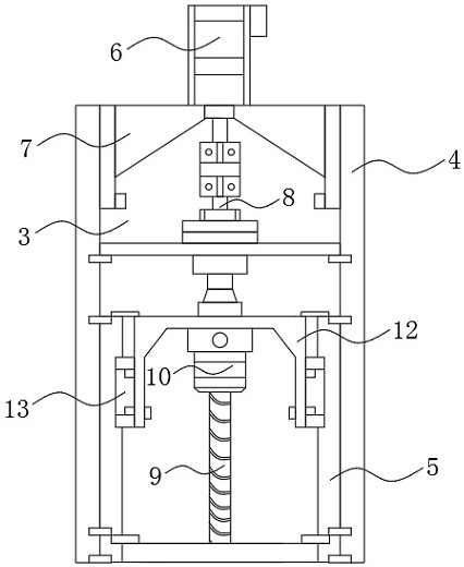
Machining equipment with tension testing function for special-shaped lifting lug

A technology of tensile testing and processing equipment, which is applied in the direction of applying stable tension/pressure to test the strength of materials, measuring devices, instruments, etc., which can solve the problem of inability to ensure that the stress point of the material to be tested is located at its axisymmetric center, and the material to be tested is clamped. The holding and fixing operation is complicated and affects the accuracy of the experimental results, so as to achieve the effect of easy and rapid reset, stable clamping and stable clamping.

Inactive Publication Date: 2021-05-14
东莞市史雷帝三维数控科技有限公司
View PDF0 Cites 1 Cited by
  • Summary
  • Abstract
  • Description
  • Claims
  • Application Information

AI Technical Summary

Problems solved by technology

[0003] The common problems of the existing lifting lug processing and testing equipment are: in order to ensure the safety of hoisting, the design and production of the lifting lug adheres to the principle of no deformation of twice the working load, and the principle of carrying four times the load without breaking; and the lifting lug should have enough Rigidity and stability, with anti-fatigue and impact resistance performance; however, the current mainstream lifting lug testing equipment in the market does not have the actual processing environment to simulate the force on both ends of the lifting lug in the actual use, and the clamping and fixing operation of the material to be tested Complicated and low in applicability, it is impossible to ensure that the stress point of the material to be tested is located at its axisymmetric center, which affects the accuracy of the experimental results

Method used


Image

  • Machining equipment with tension testing function for special-shaped lifting lug
  • Machining equipment with tension testing function for special-shaped lifting lug
  • Machining equipment with tension testing function for special-shaped lifting lug

Examples


Embodiment Construction

[0028] The following will clearly and completely describe the technical solutions in the embodiments of the present invention with reference to the accompanying drawings in the embodiments of the present invention. Obviously, the described embodiments are only some, not all, embodiments of the present invention.

[0029] In the description of the present invention, unless otherwise stated, the meaning of "plurality" is two or more; the terms "upper", "lower", "left", "right", "inner", "outer" , "front end", "rear end", "head", "tail", etc. indicate the orientation or positional relationship based on the orientation or positional relationship shown in the drawings, and are only for the convenience of describing the present invention and simplifying the description, rather than Indicates or implies that the device or element referred to must have a particular orientation, be constructed and operate in a particular orientation, and therefore should not be construed as limiting the...


PUM


Abstract

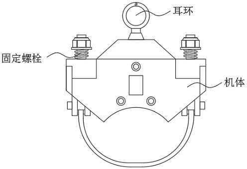
The invention discloses machining equipment with a tension testing function for a special-shaped lifting lug, which relates to the technical field of machining and detection of special-shaped components, in particular to a workbench, a lead screw tension mechanism, a connecting rod transmission mechanism, a pull rod clamping mechanism and an output end. One side of theworkbench is provided with a control end. According to the machining equipment with the tension testing function for the special-shaped lifting lug, by arranging the pull rod clamping mechanism, the problems that in the background technology, an existing tension testing mechanism is complex in operation of connecting clamping points of a to-be-detected material and depends on manual positioning are perfectly solved; a user drives the bayonet lock to rotate around the lug shaft by rotating the adjusting handle, so that the locking arm on one side of the bottom end of the bayonet lock locks the end face of the base plate, meanwhile, the eccentric block rotates under the transmission of the screw rod, and the lug part of the to-be-detected material is positioned and clamped through the output end on one side of the top end of the eccentric block, so that the clamping is stable while the operation is simple and convenient; and meanwhile, a centering effect on to-be-detected materials which are symmetric about a vertical symmetric axis is achieved.

Description

technical field [0001] The invention relates to the technical field of processing and testing of special-shaped components, in particular to a processing device with special-shaped lifting lugs with the function of tensile testing. Background technique [0002] Lifting lug is the force-bearing component installed on the equipment for lifting; the lifting lug is an important connecting part in equipment hoisting, which is directly related to the safety of large-scale equipment hoisting. Among many conveyor accessories, lifting lug is the It is an indispensable part in the operation. It is the main lifting point structure, so it requires good load-bearing capacity and stability. The strength requirements of its own strength and equipment connection. [0003] The common problems of the existing lifting lug processing and testing equipment are: in order to ensure the safety of hoisting, the design and production of the lifting lug adheres to the principle of no deformation of t...

Claims


Application Information

Patent Timeline
IPC IPC(8): G01N3/08G01N3/04
CPCG01N3/04G01N3/08G01N2203/0003G01N2203/0017G01N2203/04G01N2203/0676
Inventor 黄红梅马浩鹏石宏
Owner 东莞市史雷帝三维数控科技有限公司
Learn More