Illumination image generation method and device, equipment and medium

An image generation and image technology, which is applied in the field of image processing, can solve problems such as performance degradation of electronic equipment, large amount of calculation, and inability to meet game scenarios, etc., to achieve the effect of ensuring the authenticity of the display, increasing the amount of calculation, and optimizing the interface display effect

Active Publication Date: 2021-05-14
BEIJING BYTEDANCE NETWORK TECH CO LTD
View PDF12 Cites 1 Cited by
  • Summary
  • Abstract
  • Description
  • Claims
  • Application Information

AI Technical Summary

Problems solved by technology

[0003] At present, the number of real-time light sources that can be added in the game space is very limited, for example, usually 2-3 real-time light sources, which cannot meet the game scenes that require a large number of point light sources
Moreover, in the process of image rendering, the more real-time light sources are added, the more resources will be consumed on the electronic equipment, resulting in a sharp drop in the performance of the electronic equipment
Even if the deferred rendering strategy is adopted, the complexity of deferred rendering is proportional to the product of the number of image pixels and the number of light sources, and the amount of calculation is still very large

Method used


Image

  • Illumination image generation method and device, equipment and medium
  • Illumination image generation method and device, equipment and medium
  • Illumination image generation method and device, equipment and medium

Examples


Embodiment Construction

[0033] In order to more clearly understand the above objects, features and advantages of the present disclosure, the solutions of the present disclosure will be further described below. It should be noted that, in the case of no conflict, the embodiments of the present disclosure and the features in the embodiments can be combined with each other.

[0034] In the following description, many specific details are set forth in order to fully understand the present disclosure, but the present disclosure can also be implemented in other ways than described here; obviously, the embodiments in the description are only some of the embodiments of the present disclosure, and Not all examples.

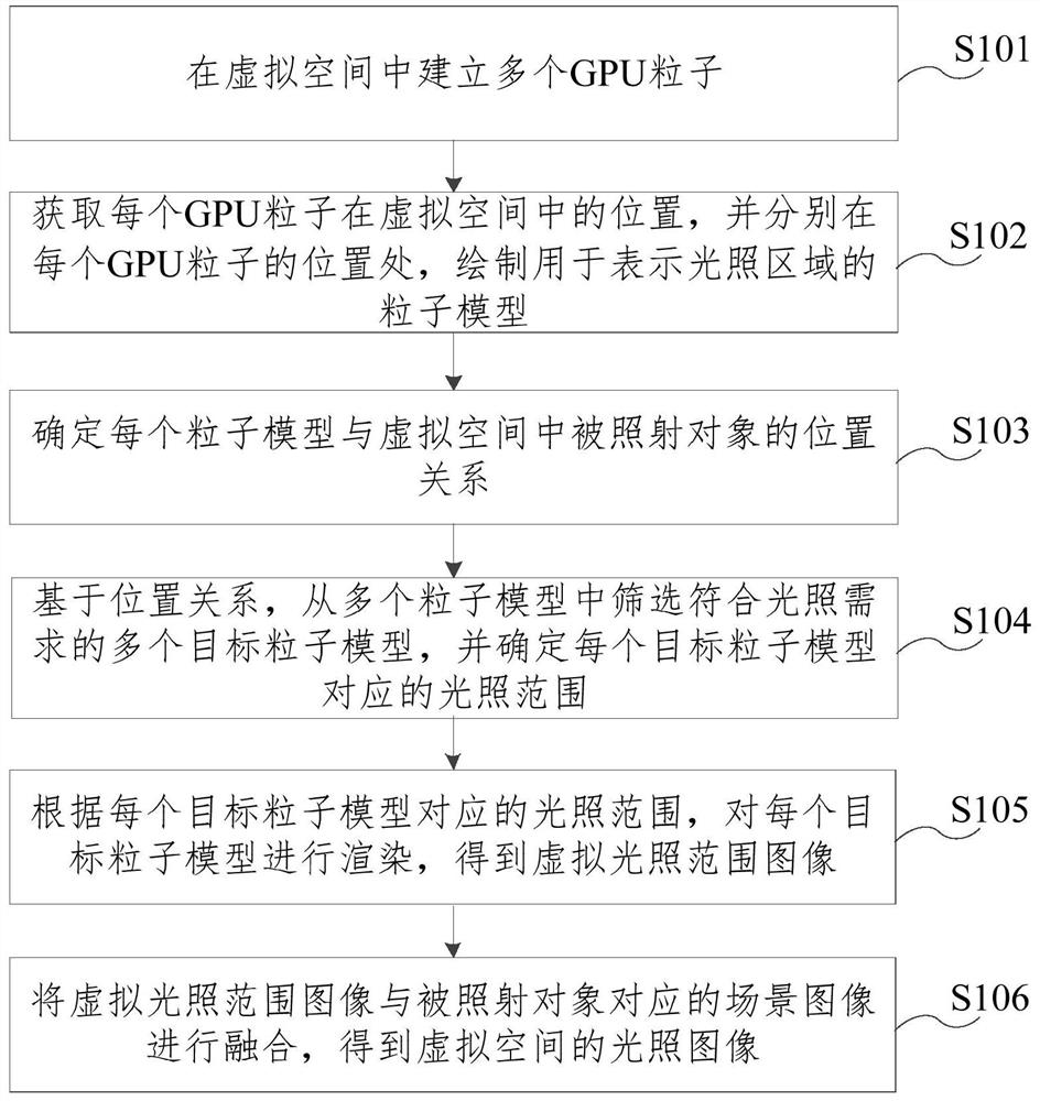
[0035] figure 1 It is a flow chart of a lighting image generation method provided by the embodiment of the present disclosure. The embodiment of the present disclosure can be applied to virtual scenes that require a large number of point light sources, such as fireflies flying, fireworks in the ...


PUM


Abstract

The embodiment of the invention relates to an illumination image generation method and device, equipment and a medium. The method comprises the steps: building a plurality of GPU particles in a virtual space; obtaining the position of each GPU particle in the virtual space, and drawing a particle model used for representing an illumination area at the position of each GPU particle; based on the position relationship between each particle model and the irradiated object in the virtual space, screening a plurality of target particle models, and determining an illumination range corresponding to each target particle model; According to the illumination range corresponding to each target particle model, rendering each target particle model to obtain a virtual illumination range image, and fusing the virtual illumination range image with a scene image corresponding to the irradiated object to obtain an illumination image of a virtual space. According to the embodiment of the invention, the calculation amount of the electronic equipment is not increased while the virtual scene needing a large number of point light sources is met, the electronic equipment with various performances can be compatible, and the interface display effect of the virtual scene on the electronic equipment is optimized.

Description

technical field [0001] The present disclosure relates to the technical field of image processing, and in particular to a method, device, device and medium for generating an illumination image. Background technique [0002] During the game development process, adding different real-time light sources to the game space can improve the scene image display effect of the game space, such as increasing the realism of the game scene. [0003] Currently, the number of real-time light sources that can be added in the game space is very limited, for example, usually 2-3 real-time light sources, which cannot satisfy game scenes that require a large number of point light sources. Moreover, in the process of image rendering, the more real-time light sources are added, the more resource consumption of the electronic device will be consumed, resulting in a sharp drop in the performance of the electronic device. Even if the deferred rendering strategy is adopted, the complexity of deferred...

Claims


Application Information

Patent Timeline
Patent Type & Authority Applications(China)
IPC IPC(8): G06T15/00G06T15/50G06T15/04G06T13/20A63F13/52
CPCG06T15/005G06T15/503G06T15/506G06T15/04G06T13/20A63F13/52G06T2210/56A63F2300/6638G06T2215/12Y02B20/40
Inventor 胡蓓欣
Owner BEIJING BYTEDANCE NETWORK TECH CO LTD
Why Eureka
Try Eureka