
Miniaturized multi-frequency antenna and manufacturing method thereof

A technology of multi-frequency antenna and manufacturing method, which is applied in the directions of antenna, antenna coupling, resonant antenna, etc., can solve the problems affecting the quality and damage of multi-frequency antenna, and achieve the effect of improving low elevation gain, increasing radiation range, and reducing antenna area

Active Publication Date: 2021-10-15
常州仁千电气科技股份有限公司
View PDF0 Cites 0 Cited by
  • Summary
  • Abstract
  • Description
  • Claims
  • Application Information

AI Technical Summary

Problems solved by technology

In the above structure, the feed pin of the ceramic antenna is connected to the ceramic dielectric layer by welding. During the welding process, due to the uneven heating inside the ceramic dielectric layer, thermal stress is generated inside the ceramic material. The ceramic material in this In some cases, local damage may occur, thereby affecting the quality of the entire multi-frequency antenna

Method used


Image

  • Miniaturized multi-frequency antenna and manufacturing method thereof
  • Miniaturized multi-frequency antenna and manufacturing method thereof
  • Miniaturized multi-frequency antenna and manufacturing method thereof

Examples


Embodiment approach

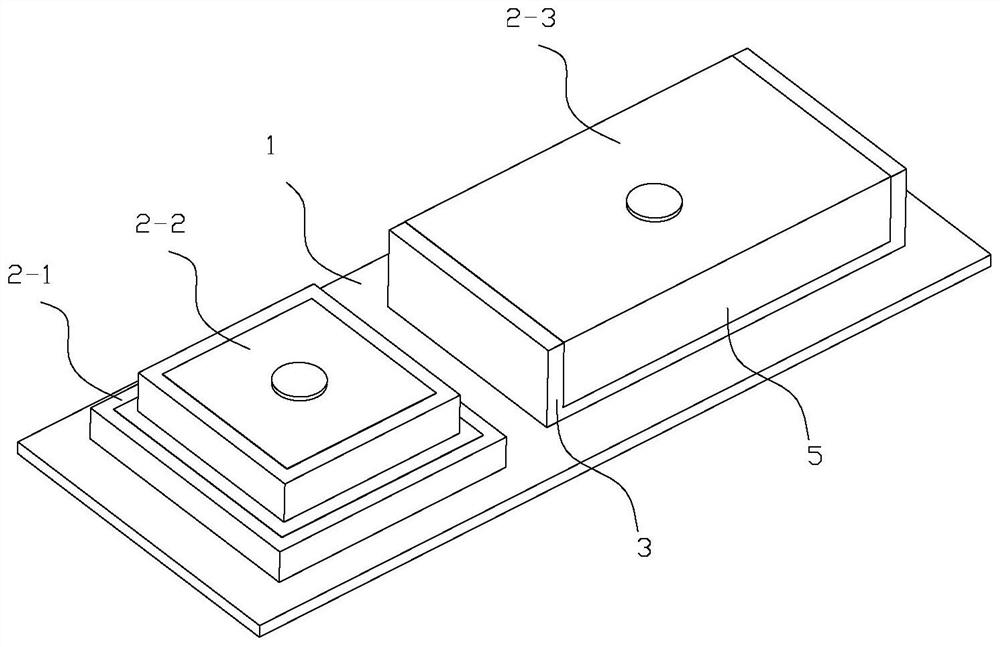
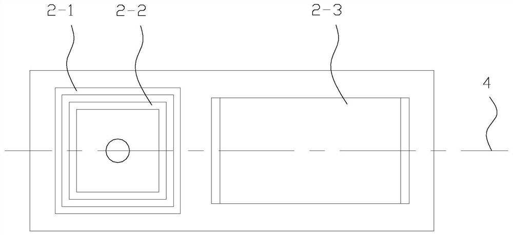
[0046] Method 1: If figure 2 As shown, a diagonal of the square is 45° to the central plane;

[0047] Method 2: If Figure 4 As shown, a diagonal of the square coincides with the central plane.

[0048] like Figure 5 As shown, the circuit board 1 is provided with a metallized hole 11 for the feed pin 6 of the ceramic antenna 2 to pass through, and the circuit board 1 is provided with a pad structure on the bottom surface opposite to the installation surface of the ceramic antenna 2. The pad structure is electrically connected, and connectors are also arranged on the side where the pad structure is located. In order to adapt to the above-mentioned method 1 and method 2, the metallized hole corresponding to the feed pin 6 of the bottom ceramic antenna 2 can be set as an arc structure on the circuit board 1, thereby increasing the versatility of the circuit board 1 and making stacking The ceramic antennas 2 can be directly rotated on the circuit board 1 of the same type to ...


PUM


Abstract

The present invention relates to the technical field of circularly polarized antennas of the Beidou system, in particular to a miniaturized multi-frequency antenna, including a circuit board, which includes at least two ceramic antennas stacked and arranged in different frequency bands and at least one ceramic antenna independently arranged , an elastic connecting piece is arranged between the feed needle and the ceramic dielectric layer, the elastic connecting piece includes an annular inner ring and an annular outer ring, and the annular inner ring and the annular outer ring are connected through the connecting end and then diffused in the axial direction Unfolding, the annular inner ring is attached to the feeder needle, and the annular outer ring is attached to the inner wall of the metal via hole on the ceramic dielectric layer. The invention effectively improves the low elevation gain of each frequency band, and avoids the damage of the ceramic dielectric layer during the welding process through the use of the elastic connecting piece. Compared with welding, the elasticity of the elastic connecting piece can deal with the collision caused by impact during use. The problem of local damage at the connection. At the same time, the present invention also claims the protection of the manufacturing method of the miniaturized multi-frequency antenna, which has the same technical effect.

Description

technical field [0001] The invention relates to the technical field of circularly polarized antennas of the Beidou system, in particular to a miniaturized multi-frequency antenna and a manufacturing method thereof. Background technique [0002] The conventional multi-frequency antennas of the Beidou system are stacked or tiled. Among them, the size of the stacked form is smaller and smaller from the bottom to the top, but the antenna frequency band bandwidth is required to be narrow, the frequency band is high, the frequency interval is large, and the hand-held The available space of the terminal is generally long, so the tiled form is more common, but the above-mentioned tiled combination method makes the size of the antenna larger, and it is difficult to be widely used in handheld terminals. [0003] In order to solve the above problems, in the prior art, multiple frequency bands are covered by a combined multi-frequency antenna of stacked ceramic antennas and independent ...

Claims


Application Information

Patent Timeline
Patent Type & Authority Patents(China)
IPC IPC(8): H01Q9/04H01Q1/52H01Q1/00
CPCH01Q1/002H01Q1/521H01Q9/0414H01Q9/0428H01Q9/045
Inventor 范炼谢征兰
Owner 常州仁千电气科技股份有限公司
Learn More