
Long-distance light dispersion compensation device

A compensating device and optical dispersion technology, applied in the direction of eliminating distortion/dispersion, optical fiber transmission, electromagnetic wave transmission system, etc., can solve problems such as complicated operation, increased equipment and cost, increased difficulty of construction and maintenance, etc., to ensure transmission distance, The effect of improving convenience

Pending Publication Date: 2021-05-14
无锡雷华网络技术有限公司
View PDF0 Cites 0 Cited by
  • Summary
  • Abstract
  • Description
  • Claims
  • Application Information

AI Technical Summary

Problems solved by technology

The existing optical fiber transmission system consists of front-end satellite receivers, signal modulators, preamplifiers, 1550nm optical transmitters, optical amplifiers, terminal receivers and other equipment; among them, the base station for signal transmission is generally tens of kilometers away from the user Even hundreds of kilometers, there is noise aggregation in such a long-distance transmission, so it is necessary to increase the conversion base station during the transmission process to ensure the integrity and distortion of the signal. After adding the conversion base station, it will increase the difficulty of construction and maintenance. At the same time, more more equipment and costs
[0003] At present, there are also externally modulated 1550nm optical transmitters that can increase the transmission distance of optical fibers on the market. The realization principle is to improve the dispersion compensation of light in the optical transmission process by optical modulation, but the debugging process requires strong professional knowledge engineering personnel. debugging, complex operation

Method used


Image

  • Long-distance light dispersion compensation device
  • Long-distance light dispersion compensation device
  • Long-distance light dispersion compensation device

Examples


Embodiment Construction

[0021] The present invention will be further described below in conjunction with specific drawings and embodiments.

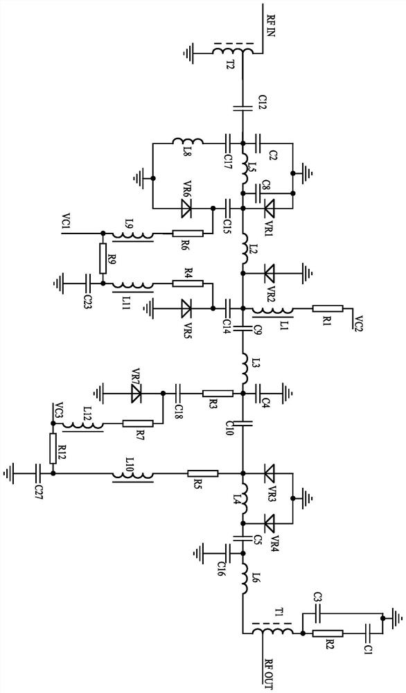
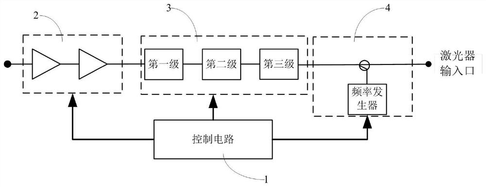
[0022] Such as figure 1 As shown: in order to effectively ensure the required transmission distance and meet the indicators after transmission, and improve the convenience of operation, the present invention includes an optical dispersion compensation circuit 3, and the optical dispersion compensation circuit 3 includes a first optical dispersion compensation circuit. Level compensation circuit, second level compensation circuit and third level compensation circuit, wherein, the first level compensation circuit, the second level compensation circuit and the third level compensation circuit are connected in sequence, and the first level compensation circuit is also connected with the input matching impedance transformation The circuit is connected, and the third-stage compensation circuit is connected with the output matching impedance transformation circuit.

...


PUM


Abstract

The invention relates to a compensation device, in particular to a long-distance light dispersion compensation device. According to the technical scheme provided by the invention, the long-distance light dispersion compensation device comprises a light dispersion compensation circuit, and the light dispersion compensation circuit comprises a first-stage compensation circuit, a second-stage compensation circuit and a third-stage compensation circuit which can perform light dispersion compensation, the first-stage compensation circuit, the second-stage compensation circuit and the third-stage compensation circuit are sequentially connected, the first-stage compensation circuit is further connected with the input matching impedance conversion circuit, and the third-stage compensation circuit is connected with the output matching impedance conversion circuit. Dispersion noise generated by long-distance optical fiber signals can be compensated, the required transmission distance is effectively ensured, indexes after transmission are met, use and operation are convenient, cost is reduced, and safety and reliability are achieved.

Description

technical field [0001] The invention relates to a compensation device, in particular to a long-distance optical dispersion compensation device. Background technique [0002] With the development of the communication industry and the improvement of user experience, the received network signals and video signals are required to be more stable, enhanced, and efficient, thereby realizing the fiber-to-the-home transmission system. The existing optical fiber transmission system consists of front-end satellite receivers, signal modulators, preamplifiers, 1550nm optical transmitters, optical amplifiers, terminal receivers and other equipment; among them, the base station for signal transmission is generally tens of kilometers away from the user Even hundreds of kilometers, there is noise aggregation in such a long-distance transmission, so it is necessary to increase the conversion base station during the transmission process to ensure the integrity and distortion of the signal. Aft...

Claims


Application Information

Patent Timeline
IPC IPC(8): H04B10/2513
CPCH04B10/25133
Inventor 万年飞林文军张满根
Owner 无锡雷华网络技术有限公司
Learn More