

Multi rotor unmanned aerial vehicle with high brightness air illumination
A multi-rotor unmanned aerial vehicle, high-brightness technology, applied in the field of unmanned aerial vehicles, can solve the problem of not having high-brightness aerial lighting function, etc., and achieve the effects of wide power supply range, high flexibility, and improved efficiency
- Summary
- Abstract
- Description
- Claims
- Application Information
AI Technical Summary
Problems solved by technology
Method used
Image

Examples
Embodiment Construction
[0031] Now describe in detail the structural features of the present invention in conjunction with the accompanying drawings.
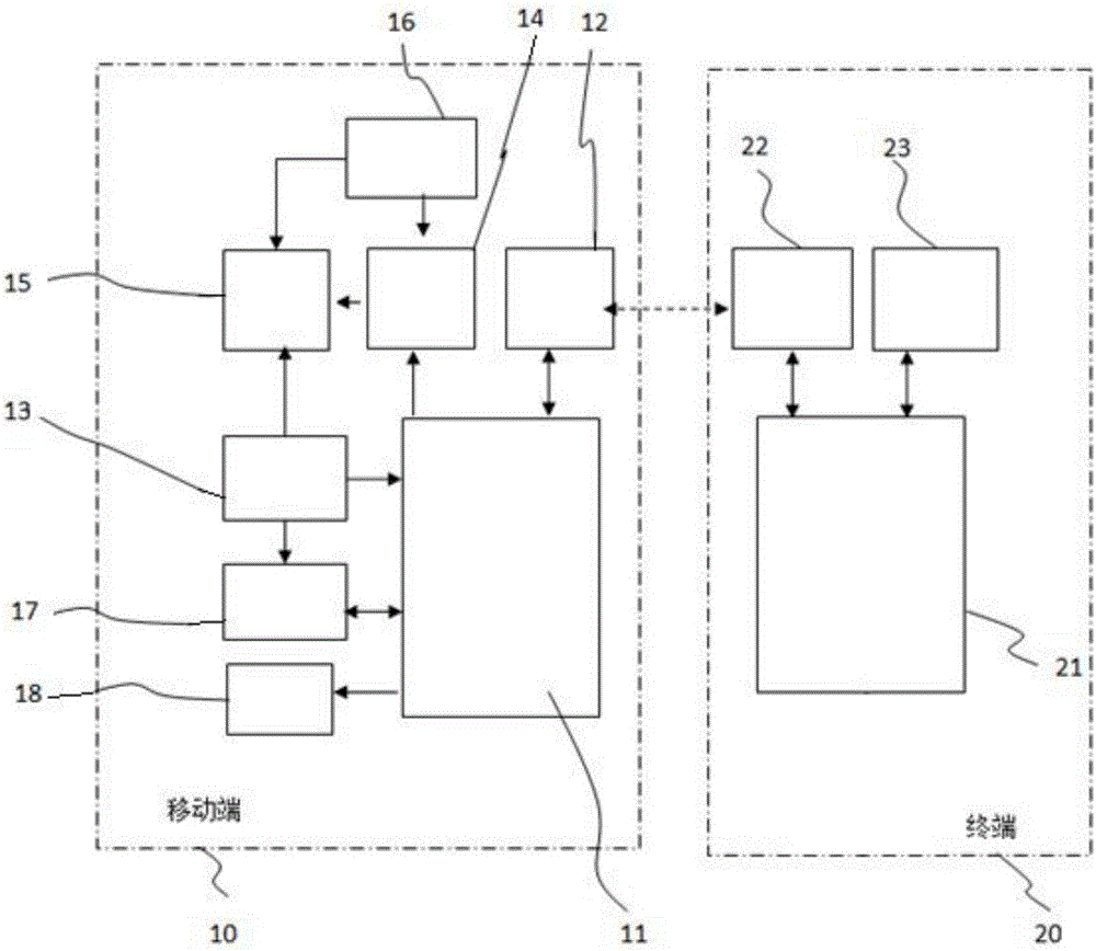
[0032] A multi-rotor drone with high-brightness aerial lighting, see figure 1 , including a mobile terminal 10 and a terminal 20, the mobile terminal 10 is installed on the multi-rotor UAV, and the terminal 20 is installed in the ground receiving station;
[0033] Wherein, the mobile terminal 10 includes a mobile terminal central processing unit 11, a mobile terminal data transmission module 12, a mobile terminal remote control receiver module 13, a mobile terminal LED lamp power control module 14, a mobile terminal LED lamp 15, and a mobile terminal steering gear 16; specifically , the mobile terminal central processing unit 11 is respectively connected with the mobile terminal data transmission module 12, the mobile terminal remote control receiver module 13, and the mobile terminal LED light power control module 14; 20, the mobile terminal central...
PUM
 Abstract
Description
Claims
Application Information