
A wear-resistant and corrosion-resistant sliding cable for mine optoelectronic composite

A photoelectric composite and corrosion-resistant technology, which is applied to power cables with shielding layers/conductive layers, communication cables, insulated cables, etc., can solve problems affecting cable protection life, cable fatigue, shrinkage increase, etc., to ensure communication capacity and transmission distance, increase the cross-section of the ground wire, and reduce the effect of light loss

Active Publication Date: 2020-08-14
湖南华菱线缆股份有限公司
View PDF2 Cites 0 Cited by
  • Summary
  • Abstract
  • Description
  • Claims
  • Application Information

AI Technical Summary

Problems solved by technology

The cable realizes the photoelectric composite, but structurally, the optical fiber and the control line must be twisted together with the power line to form the cable core, the optical fiber is in a spiral bending shape, the optical loss increases significantly, and the communication bandwidth and transmission length decrease; secondly, when the cable is bent, The optical fiber is bound to be subjected to tensile force, and the optical fiber is easy to break under the action of frequent repetitions; in addition, the steel tape armor layer makes the cable hard, and the bending property is sharply reduced. Working conditions
During the use of the cable, frequent power on-off switching will cause the temperature to fluctuate greatly. Due to the frequent changes in temperature, the stress and strain of the cable material are called temperature self-stress and temperature self-strain. From a mechanical point of view, it belongs to compressive stress and compression. The strain property is mainly due to the constraints of the terminal and joint space, which will lead to cable fatigue, increased plastic deformation, and increased shrinkage. Unlike ordinary "thermal expansion and contraction", thermal contraction is an irreversible process, so It will affect the insulation life and performance. The temperature change of the sheath material is smaller than that of the insulation sheath, but the fatigue creep will also affect the cable protection life to a certain extent.
[0005] At the same time, the material of the cable outer sheath is easily affected by factors such as mine environment moisture, sulfide, heavy metals or air oxidation during use, and will gradually corrode the sheath and insulation layer, exposing the cable core to the air or multiple cables The cores contact each other to generate arcs, resulting in short circuits, large-scale power outages, and even gas explosions, causing accidents
[0006] Chinese patent 201810792838.7 discloses a high flame-retardant and corrosion-resistant cable material. Although the flame retardant has been improved in its technical solution and the amount of flame retardant used has been reduced, the phenylguanidine carbonate used in the technical solution When the salt encounters an acidic environment, it is easy to generate carbon dioxide, which in turn causes the cable material to foam, and the expanded vermiculite and diatomaceous earth used are also easy to expand, and the cable material is prone to strain effect when the temperature rises, which increases the production of the cable material. Arcing effect, short-circuit fire hazard, and reduced service life; therefore, although flame retardants and corrosion-resistant agents are used in cable materials, the danger of burning caused by its deformation greatly exceeds its flame-retardant and corrosion-resistant components for cable materials Insulation safety performance

Method used


Image

  • A wear-resistant and corrosion-resistant sliding cable for mine optoelectronic composite
  • A wear-resistant and corrosion-resistant sliding cable for mine optoelectronic composite
  • A wear-resistant and corrosion-resistant sliding cable for mine optoelectronic composite

Examples


Embodiment 1

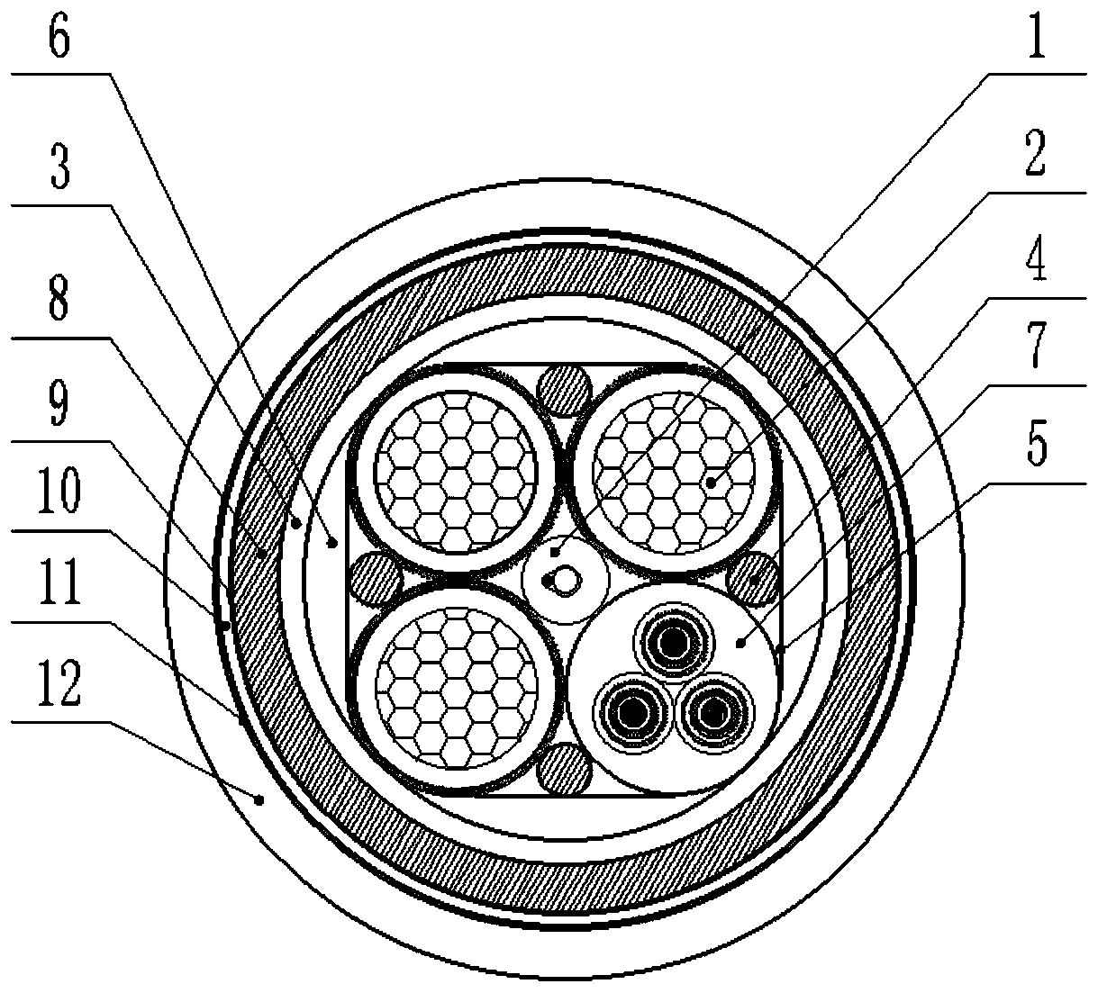
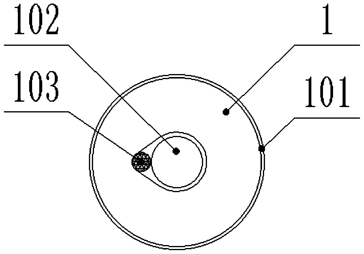
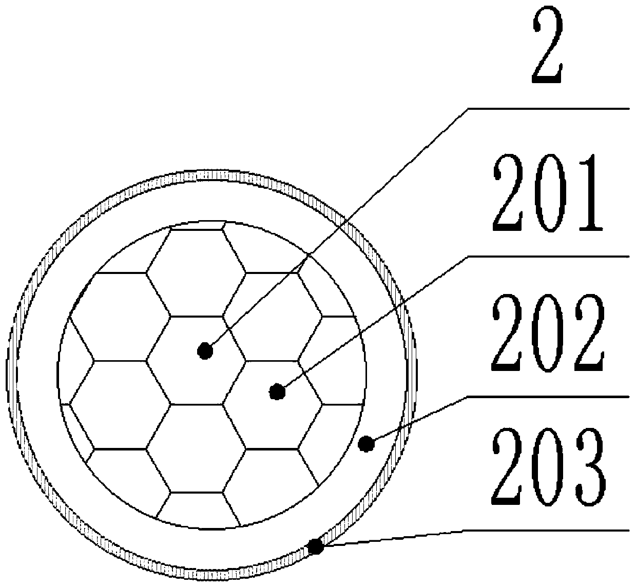
[0070] Such as Figure 1-4 As shown; the wear-resistant and corrosion-resistant sliding cable for mine photoelectric composite of the present embodiment includes functional components, inner sheath 8 and outer sheath 12 from inside to outside in turn; inner sheath 8 and outer sheath 12 are provided with Slip layer; the functional components include an optical fiber group 1 and three power lines 2 twisted around the optical fiber group 1, a control line group 7 and multiple reinforcing strips 4, and the functional components are bundled with high-strength fibers 5 after twisting, The high-strength fibers 5 are fiber ropes 71 with 12 strands crossing forward and backward, bundled at an angle of 45° relative to the radial direction of the cable; the optical fiber group 1 includes steel wires 103, optical fibers 102 and metal sleeves 101, steel wires 103 and optical fibers 102 Covered in the metal sleeve 101, the maximum outer diameter of the single-mode optical fiber is 0.5 times...

Embodiment 2

[0100] Such as Figure 1-4 As shown; the wear-resistant and corrosion-resistant sliding cable for mine photoelectric composite of the present embodiment includes functional components, inner sheath 8 and outer sheath 12 from inside to outside in turn; inner sheath 8 and outer sheath 12 are provided with Slip layer; the functional components include an optical fiber group 1 and three power lines 2 twisted around the optical fiber group 1, a control line group 7 and multiple reinforcing strips 4, and the functional components are bundled with high-strength fibers 5 after twisting, The high-strength fiber 5 is a fiber rope 71 with 4 strands crossing forward and backward, and is bundled at an angle of 30° relative to the radial direction of the cable; the optical fiber group 1 includes steel wire 103, optical fiber 102 and metal sleeve 101, steel wire 103 and optical fiber 102. Covered in the metal sleeve 101, the maximum outer diameter of the single-mode optical fiber is 0.3 time...

Embodiment 3

[0130] Such as Figure 1-4 As shown; the wear-resistant and corrosion-resistant sliding cable for mine photoelectric composite of the present embodiment includes functional components, inner sheath 8 and outer sheath 12 from inside to outside in turn; inner sheath 8 and outer sheath 12 are provided with Slip layer; the functional components include an optical fiber group 1 and three power lines 2 twisted around the optical fiber group 1, a control line group 7 and multiple reinforcing strips 4, and the functional components are bundled with high-strength fibers 5 after twisting, The high-strength fiber 5 is a fiber rope 71 with 8 strands crossing each other in the front and back, and is bundled at an angle of 40° relative to the radial direction of the cable; the optical fiber group 1 includes steel wire 103, optical fiber 102 and metal sleeve 101, steel wire 103 and optical fiber 102 package Covered in the metal sleeve 101, the maximum outer diameter of the single-mode optica...


PUM

PropertyMeasurementUnit
verticalityaaaaaaaaaa
diameteraaaaaaaaaa

Abstract

The invention discloses a mine photoelectric composite wear-resisting and corrosion-resisting sliding cable comprising a functional component, an inner sheath and an outer sheath which are arranged from inside to outside in turn. A sliding layer is arranged between the inner sheath and the outer sheath. The functional component comprises an optical fiber group and three power lines, one control line group and multiple reinforcing strips which are twisted around the optical fiber group. The functional component is twisted and then bundled with high-strength fibers. The outer periphery of the functional component is provided with a non-metal reinforcing layer. The outer periphery of the non-metal reinforcing layer is provided with the inner sheath. The inner side of the outer sheath is provided with an isolation film. The cable is more flexible and stable in structure. The bending radius can be less than 3 times of the cable diameter, and the bending times are more than 30000 times which are higher than the 9000 times specified in the standard MT818. The cable is subjected to long-term, frequent and repeated bending and straightening and the conductors and the optical fibers are not broken so that the problems existing in the prior art can be effectively solved.

Description

technical field [0001] The invention relates to the field of cables, in particular to a wear-resistant and corrosion-resistant sliding cable for mine photoelectric composite. Background technique [0002] With the development of the coal industry, the situation of underground safety production is becoming increasingly severe. How to reduce the casualties and property losses caused by underground accidents is the focus of our practitioners' consideration now and in the future. This patent provides a wear-resistant and corrosion-resistant sliding cable for mine photoelectric composite, which helps to realize the intelligence of underground mining operations, reduce the number of underground operators, and thereby reduce the risks caused by safety accidents. [0003] Usually, the shearer cable usually includes 3 power cores, 1 ground wire and several control wires. This structure can only realize the power transmission of the equipment and simple signal control, which cannot me...

Claims


Application Information

Patent Timeline
Patent Type & Authority Patents(China)
IPC IPC(8): H01B7/00H01B7/04H01B7/18H01B7/17H01B7/28H01B7/285H01B9/02H01B11/00G02B6/44C08L23/34C08L23/16C08L79/04C08L75/02C08K13/06C08K3/04C08K9/10C08K5/47C08K7/18C08K3/22
CPCC08K2003/2224C08L23/16C08L23/34C08L2203/202C08L2205/025C08L2205/035G02B6/4432H01B7/0009H01B7/0045H01B7/041H01B7/17H01B7/18H01B7/1825H01B7/183H01B7/1835H01B7/1895H01B7/2806H01B7/285H01B9/02H01B11/00C08L79/04C08L75/02C08K13/06C08K3/042C08K9/10C08K5/47C08K7/18C08K3/22
Inventor 马辽林李华斌张公卓张文钢姚文忠
Owner 湖南华菱线缆股份有限公司
Learn More