Die attach systems, and methods of attaching die to substrate

A technology of die and substrate, applied in the field of die attach system and attaching die to substrate, which can solve the problems of speed accumulation and complexity

Pending Publication Date: 2021-05-14
安必昂公司
View PDF0 Cites 0 Cited by
  • Summary
  • Abstract
  • Description
  • Claims
  • Application Information

AI Technical Summary

Problems solved by technology

[0006] There are often complexities associated with such applications (those that do not use pick and place operations)
For example, the speed of the die attach operation and the associated

Method used


Image

  • Die attach systems, and methods of attaching die to substrate
  • Die attach systems, and methods of attaching die to substrate
  • Die attach systems, and methods of attaching die to substrate

Examples


Embodiment Construction

[0019] As used herein, the term "die" is intended to refer to any structure that includes (or is configured to include in a later step) a semiconductor chip or die. Exemplary "die" elements include: bare semiconductor dies including bare LED semiconductor dies, semiconductor tubes on substrates (e.g., leadframes, PCBs, carriers, semiconductor chips, semiconductor wafers, BGA substrates, semiconductor components, etc.) core, packaged semiconductor device, flip chip semiconductor device, die embedded in a substrate, and others.

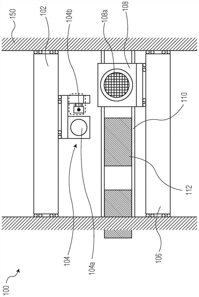
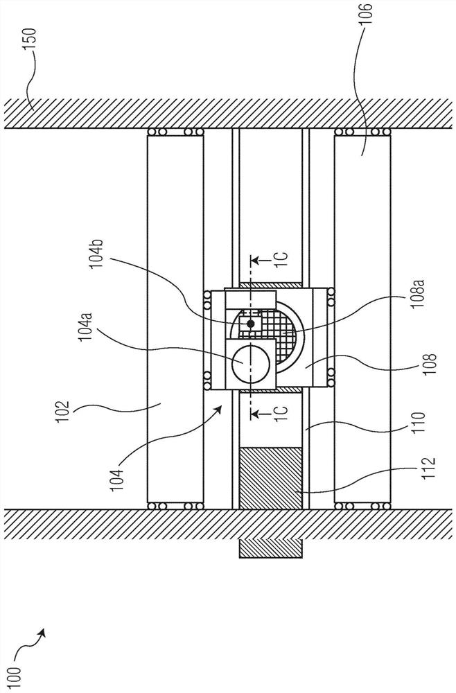
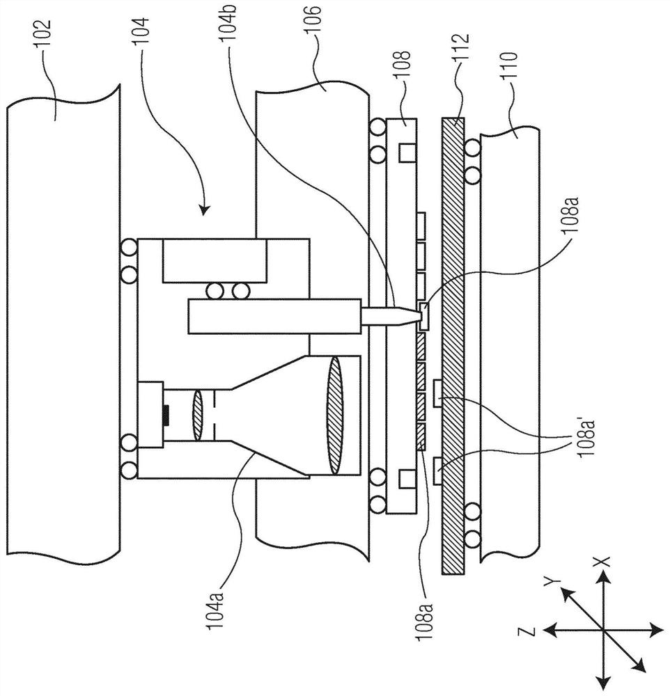
[0020] According to certain exemplary embodiments of the present invention, there is provided a die attach system comprising an inventive arrangement for supporting a solder tip or a die supply. Such devices include: (i) a long stroke portion supporting a short stroke axis; and (ii) a short stroke portion supporting a solder tip or die supply. For example, during a bonding sequence, the long travel axis may travel at a constant speed relative to the su...


PUM


Abstract

A die attach system is provided. The die attach system includes a support structure for supporting a substrate; a die supply source including a plurality of die for attaching to the substrate; a bond head for bonding a die from the die supply source to the substrate, including a bond tool for contacting the die during a transfer from the die supply source to the substrate; a first motion system for moving the bond head along a first axis; and a second motion system, independent of the first motion system, for moving the bond tool along the first axis.

Description

[0001] Cross References to Related Applications [0002] This application claims the benefit of U.S. Provisional Application No. 62 / 726,387, filed September 3, 2018, the contents of which are incorporated herein by reference. technical field [0003] The present invention relates to systems and methods for attaching dies to substrates, and more particularly, to improved systems and methods for attaching dies to substrates without picking the dies from a die supply. Background technique [0004] With regard to mounting die on a substrate (eg, mounting a semiconductor die on a substrate), many conventional applications employ "pick and place" operations. In such operations, dies are "picked" from a semiconductor wafer or other die supply source, and the dies are then moved to (and "mounted" on) a target substrate. Such operations also employ one or more transfers between the "pick" tool and the "place" tool. [0005] Some die attach applications do not use pick and place ope...

Claims


Application Information

Patent Timeline
IPC IPC(8): H01L21/683H01L21/67
CPCH01L24/75H01L21/6836H01L2221/68318H01L2221/68309H01L2221/68363H01L2224/75301H01L2224/16227H01L2924/15311H01L25/0753H01L33/62H01L2933/0066H01L21/6835H01L2221/68354
Inventor R·布鲁韦尔R·A·范德布尔格R·H·赫夫斯W·G·范斯普朗
Owner 安必昂公司
Why Eureka
Try Eureka