An environment-friendly straw resource efficient treatment system

A straw resource and processing system technology, applied in chemical instruments and methods, electrode cleaning, agricultural machinery and implements, etc., can solve problems such as machine jamming, low willingness to work, dust pollution, etc., to achieve guaranteed crushing effect and good crushing effect , the effect of reducing wear

Active Publication Date: 2021-12-21
河南鸣皋智能科技有限公司
View PDF6 Cites 0 Cited by
  • Summary
  • Abstract
  • Description
  • Claims
  • Application Information

AI Technical Summary

Problems solved by technology

However, too much feeding will easily cause the machine to be stuck, and the excess straw will also fall out from the feeding port, requiring workers to pick up the materials again, which will greatly reduce the work efficiency.
In addition, a large amount of dust pollution will be generated when crushing straw, the working environment of workers is poor, and the willingness to work is low, which seriously restricts the development of the industry

Method used


Image

  • An environment-friendly straw resource efficient treatment system
  • An environment-friendly straw resource efficient treatment system
  • An environment-friendly straw resource efficient treatment system

Examples


Embodiment 1

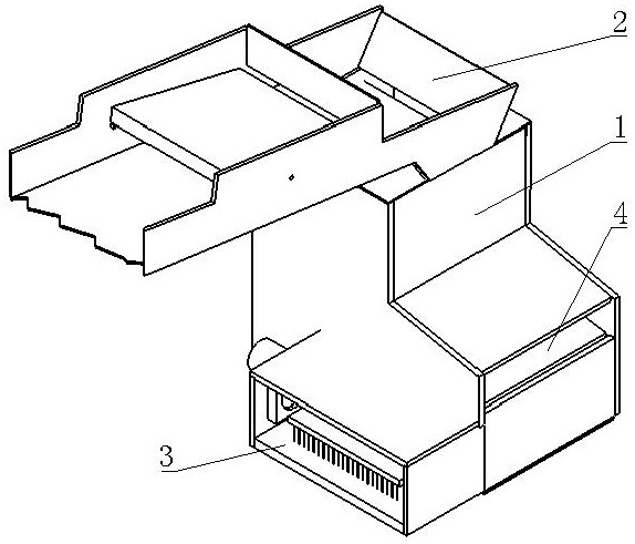
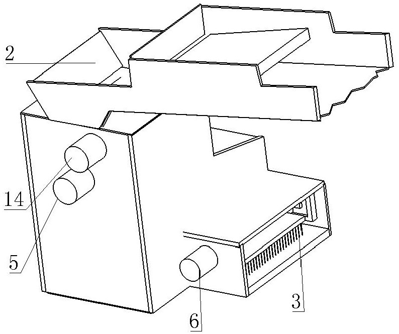
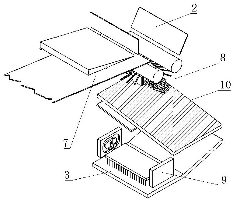
[0046] An environment-friendly straw resource efficient treatment system, such as figure 1 , figure 2 , image 3 As shown, a housing 1 is included, and a feeding device 7 is arranged in the housing 1, and a feeding port 2 matched with the feeding device 7 is provided on one side of the feeding device 7; a pair of feeding devices are arranged below the feeding port 2 The feed roller is connected with a motor, and the gap between the feed rollers is connected to the feed port 2; a cutting device 8 is arranged below the feed roller, and the cutting device 8 matches the gap between the feed rollers; A vibrating screen 10 is arranged below the material cutting device 8, and the gap between the vibrating screen 10 and the feeding roller is matched; the first discharge port 4 and the second discharge port that are matched with the vibrating screen 10 are opened on the shell 1 3. The first discharge port 4 communicates with the top of the vibrating screen 10, and the second dischar...

Embodiment 2

[0056] The difference between this embodiment and Embodiment 1 lies in that a second limiting block 706 is fixedly connected to the side plate.

[0057] Such as Figure 12 As shown, the second limit block 706 is arranged below the feeding section of the material holding plate 701. When the lower feeding section rotates downward, the second limit block 706 limits the position of the feeding section to prevent the material holding plate 701 from wearing the conveyor belt. 704.

Embodiment 3

[0059] The difference between this embodiment and Embodiment 1 is that a water distribution pipe is arranged in the kneading plate 901 .

[0060] Such as Figure 13 As shown, a cooling water pipe is arranged in the kneading material plate 901 to prevent the frictional overheating of the kneading material plate 901. 15 and the water outlet pipe 16, the water inlet pipe 15 and the water outlet pipe 16 are flexible pipes, and the housing 1 is provided with a through hole above the kneading material plate 901.


PUM


Abstract

An environment-friendly high-efficiency treatment system for straw resources, comprising a housing, a feeding device is arranged inside the housing, and a feeding port matching the feeding device is arranged on one side of the feeding device; a pair of feeding ports are arranged below the feeding port. Feed roller, the feed roller is connected with a motor, and the gap between the feed rollers is connected to the feed port; a cutting device is installed under the feed roller, and the cutting device matches the gap between the feed rollers; the cutting device A vibrating screen is arranged below, and the gap between the vibrating screen and the feeding roller matches; the first discharge port and the second discharge port matching the vibrating screen are opened on the shell; the first discharge port and the vibrating screen The top is connected, and the second discharge port is connected with the bottom of the vibrating screen; a conveying mechanism is arranged directly below the vibrating screen; a kneading device is provided between the conveying mechanism and the second discharge port; the invention provides a convenient feeding, crushing effect A good environment-friendly and efficient treatment system for straw recycling.

Description

technical field [0001] The invention belongs to the technical field of organic solid waste treatment and resource utilization, and in particular relates to an environment-friendly efficient treatment system for straw resource utilization. Background technique [0002] Crop stalks placed in the field will affect the growth of crops. After the crops are harvested, the discarded crop stalks need to be disposed of to ensure the yield of the next crop. In the past, people often used the method of burning straw in the field, but because burning straw pollutes the environment and also endangers people's safety, so now straw is usually reused, such as making feed, making biogas, etc. Reusing the straw requires pretreatment of the straw, usually the straw is crushed first, and then processed in other ways. [0003] After the straw is crushed, it can be pelletized and used as feed. Granulation needs to grind the crushed straw, and then squeeze the ground straw through the mesh to ob...

Claims


Application Information

Patent Timeline
Patent Type & Authority Patents(China)
IPC IPC(8): A01F29/00A01F29/04A01F29/09A01F29/08A01F29/10A01F29/12A01F29/14B07B1/28B07B1/42B07B1/46B08B5/04B03C3/12B03C3/76B03C3/88
CPCA01F29/005A01F29/04A01F29/09A01F29/08A01F29/10A01F29/12A01F29/14B07B1/28B07B1/42B07B1/46B08B5/04B03C3/12B03C3/76B03C3/88
Inventor 王菁李广辉魏志萍仝学先王婷婷杨新焕陈丰年姜永涛高敬团吴亚南王倩张博尚晓琰王基沣王丽华
Owner 河南鸣皋智能科技有限公司
Why Eureka
Try Eureka