Method capable of automatically smearing coupling agent on ultrasonic probe

A technology of ultrasonic probe and coupling agent, which is applied in the directions of ultrasonic/sonic/infrasonic diagnosis, ultrasonic/sonic/infrasonic Permian technology, ultrasonic/sonic/infrasonic image/data processing, etc. Intelligent control of spraying couplant, inconvenient use by medical staff, etc.

Inactive Publication Date: 2021-05-18
赵晓辉
View PDF2 Cites 0 Cited by
  • Summary
  • Abstract
  • Description
  • Claims
  • Application Information

AI Technical Summary

Problems solved by technology

[0005] However, the above-mentioned prior art still requires manual spraying of the couplant, and the amount of the sprayed couplant cannot be intelligently controlled according to the conditions of different patients, which is inconvenient for medical staff to use, and the experience is not strong.

Method used


Image

  • Method capable of automatically smearing coupling agent on ultrasonic probe
  • Method capable of automatically smearing coupling agent on ultrasonic probe
  • Method capable of automatically smearing coupling agent on ultrasonic probe

Examples


Embodiment 1

[0042]Such asFigure 6 As shown, the present invention also provides a method of automatically discomiting a coupling agent on an ultrasonic probe, using the above device, including the following steps:

[0043]Step 1: When the ultrasonic probe is placed on the patient, the substrate 2-8 in the pressure sensor extruded the cantilever beam 2-3, resulting in a change in the resistance value of strain sheet 2-2 and is considered to be inspected for the patient, and the microcontroller 1 -1 Control air pump module 1-2 spray a small amount of coupling agent; the single-chip unit 1-1 calculates the thickness of the fat according to the data monitored by the ultrasonic probe module 1-4, and calculates the amount of spray coupling agent according to the fat thickness, and the formula of the fat thickness is H = (t * v) / 2, where h indicates the fat thickness, T represent time, V represents the propagation speed of ultrasonic waves; the formula of the spray coupling dose L1 is L1 = D * x * h, w...

Embodiment 2

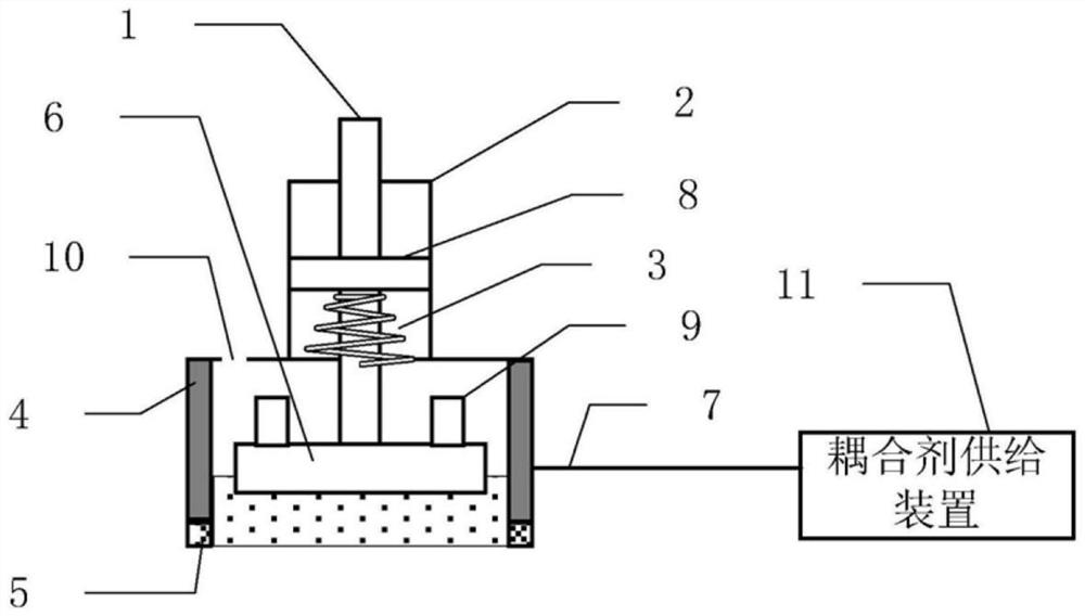
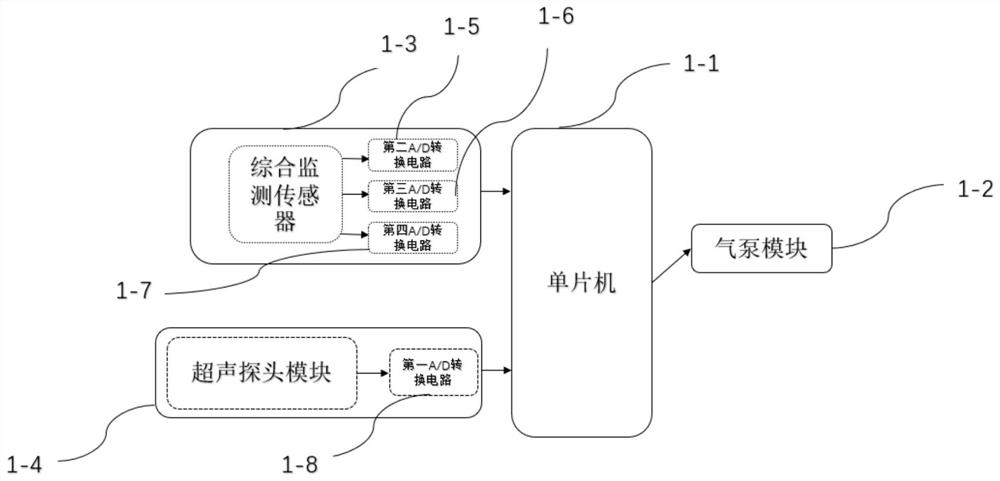
[0048]Such asFigure 3-5As shown, an apparatus capable of moving a coupling agent on an ultrasonic probe includes an ultrasonic probe module 1-4, an integrated monitoring sensor 1-3, a single chip 1-1, a gas pump module 1- 2, nozzle 3-1; the ultrasonic probe module 1-4, integrated monitoring sensor 1-3, air pump module 1-2 is connected to single chip 1-1; the gas pump module 1-2 passes through the hose and spout 3- 1 connection.

[0049]The ultrasonic probe module 1-4 includes generators and receivers that transmit ultrasonic waves to the patient, the receiver receives an ultrasonic echo signal, and the ultrasonic echo signal is converted into a number through the first A / D conversion circuit 1-8. The ultrasonic echo signal is transmitted to the single-chip unit 1-1 again to perform calculation processing.

[0050]Further, the single-chip unit 1-1 extracts the digital ultrasonic echo signal and identifies it, identifies that the individual fat layers under the skin received by the ultras...


PUM


Abstract

The invention provides a method capable of automatically smearing a coupling agent on an ultrasonic probe. The method comprises the following steps: Step 1, when the ultrasonic probe is placed on the body of a patient, the quantity of the sprayed coupling agent is calculated according to fat thickness; Step 2, a comprehensive monitoring sensor starts to monitor the coupling agent sprayed in the step 1; Step 3, the method in the step 2 is repeated to monitor the coupling agent on the patient, and the quantity of the coupling agent needing to be sprayed is obtained by the single chip microcomputer according to the calculation formula in the step 2; and Step 4, when the resistance value of a strain gauge in the step 1 stops changing, it is regarded that monitoring of the patient is completed, and the comprehensive monitoring sensor stops monitoring.

Description

Technical field[0001]The present invention relates to the field of ultrasonic probes, and more particularly to a method of automatically discomating coupling in an ultrasonic probe.Background technique[0002]When the ultrasound examination, the air between the probe and the patient will hinder the ultrasonic transmission into the human body, in order to obtain high quality clear images, the liquid conduction medium needs to be used to connect the probe and the patient, this medium is commonly used ultrasonic coupling agent. . The purpose of using ultrasonic coupling is first is the tiny void between the contact surfaces, and does not affect the micro air between these voids, the secondary penetration of the ultrasound; the second is "transition" by the coupling, so that the acoustic impedance between the probe and the skin The difference is reduced, thereby reducing the reflection loss of ultrasound energy at this interface. In addition, it also plays a "lubrication" action, reducing...

Claims


Application Information

Patent Timeline
IPC IPC(8): A61B8/00A61B8/08A61M35/00
CPCA61B8/0833A61B8/4281A61B8/4444A61M35/20
Inventor 赵晓辉
Owner 赵晓辉
Why Eureka
Try Eureka