Cryoablation catheter
A technology for ablation catheters and catheters, applied in catheters, cooling surgical instruments, medical science and other directions, can solve the problems of long pre-cooling time of cryo-catheters, increased risk of clinical use, and high use pressure of cryo-catheters
- Summary
- Abstract
- Description
- Claims
- Application Information
AI Technical Summary
Problems solved by technology
Method used
Image

Examples
Embodiment 1
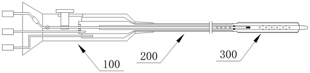
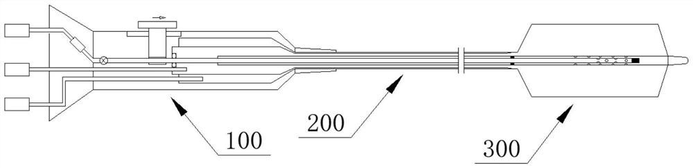
[0068] Such as Figure 1-8 As shown, a cryoablation catheter includes a catheter 200, a handle 100 at the proximal end of the catheter 200, and a balloon 300 at the distal end of the catheter. Among them, the proximal end refers to figure 1 , 2 Left orientation is indicated, distal is indicated in right orientation.
[0069] Several pipelines are arranged in the handle 100 , including an air inlet pipe 110 for connecting with an air source, an air return pipe 120 for connecting with an exhaust mechanism, and a vacuum pipe 130 for connecting with a vacuum device. The balloon 300 includes a foldable balloon, and the balloon can be any known existing balloon. The cryoablation catheter is precooled as figure 1 As shown, the balloon 300 is folded at this time, and it is as shown in the cryoablation figure 2 As shown, the balloon 300 is now inflated.
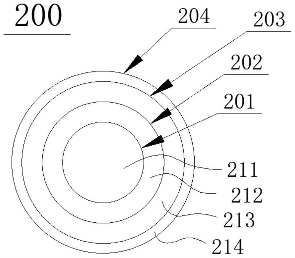
[0070] Such as Figure 3a As shown, the conduit 200 may include a first conduit 201, a second conduit 202, a third conduit 2...
Embodiment 2
[0085] Such as Figure 9a , 9b As shown, a cryoablation catheter has the same main structure as that of Embodiment 1, the difference lies in the structure of the sealing assembly for separating the two nozzle assemblies. Specifically,
[0086] To isolate the first orifice assembly 221 from the second orifice assembly 222 , the cryoablation catheter includes a baffle 232 hingedly disposed on the inner wall of the sealing area 2021 of the second catheter 202 . When the baffle 232 is in the closed position, the second conduit 202 is divided into two parts by it, the first conduit 201 is located in the proximal part, the second nozzle assembly 222 is located in the distal part separated by it, and the first nozzle assembly 221 is not in communication with the second nozzle assembly 222 . After the first conduit 201 is displaced to the distal end, the baffle 232 is opened, for example pushed away by the first conduit 201, the baffle 232 is in the open position, and the distal en...
Embodiment 3
[0091] Such as Figure 10a , 10b As shown, a cryoablation catheter, the main structure of which is the same as that of the second embodiment, the difference is that the structure of the distal end of the first catheter 201 is different.
[0092] Specifically, the distal end of the first conduit 201 is an open distal port, and the through hole 2013 on the side wall of the distal end of the first conduit 201 is also canceled; that is, the structure of the distal end of the first conduit 201 is determined by the embodiment The closed distal point in 1 and 2 is composed of several through holes 2013 arranged adjacent to the distal point, and becomes only formed by the open distal port 2014 . Other structures and working processes are the same as those in Embodiment 2.
PUM
 Abstract
Description
Claims
Application Information
 - R&D
- Intellectual Property
- Life Sciences
- Materials
- Tech Scout
- Unparalleled Data Quality
- Higher Quality Content
- 60% Fewer Hallucinations
Browse by: Latest US Patents, China's latest patents, Technical Efficacy Thesaurus, Application Domain, Technology Topic, Popular Technical Reports.
© 2025 PatSnap. All rights reserved.Legal|Privacy policy|Modern Slavery Act Transparency Statement|Sitemap|About US| Contact US: help@patsnap.com