Plastic cleaning equipment

A plastic cleaning and equipment technology, applied in plastic recycling, cleaning methods and utensils, cleaning methods using tools, etc., can solve problems such as large buoyancy, reduced performance, time-consuming and labor-intensive cleaning, etc.

Inactive Publication Date: 2021-05-18
见才福
View PDF4 Cites 6 Cited by
  • Summary
  • Abstract
  • Description
  • Claims
  • Application Information

AI Technical Summary

Problems solved by technology

[0005] Aiming at the deficiencies of the prior art, the present invention provides a plastic cleaning equipment, which solves the problem that the existing plastic cleaning equipment can only clean ordinary plastics, and for those plastics with flake particles and large floating, a large number of flake plastics Particles float on the water surface, forming a floating layer, increasing the buoyancy, and it is very difficult to clean. The cleaning equipment has great limitations, which makes cleaning time-consuming and laborious, and the cleaning efficiency is low, which reduces the problem of performance.

Method used


Image

  • Plastic cleaning equipment
  • Plastic cleaning equipment
  • Plastic cleaning equipment

Examples


Embodiment example 1

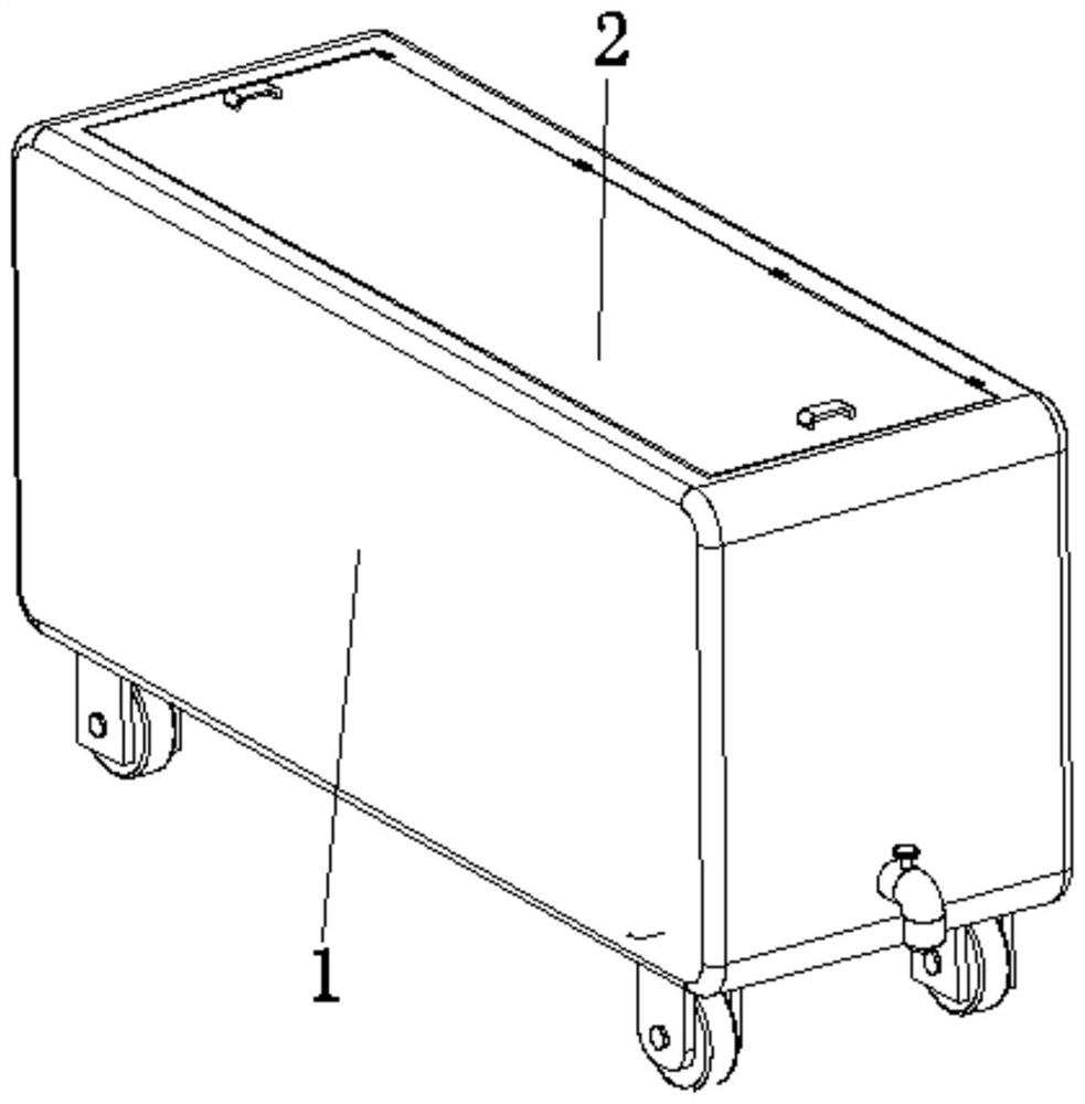
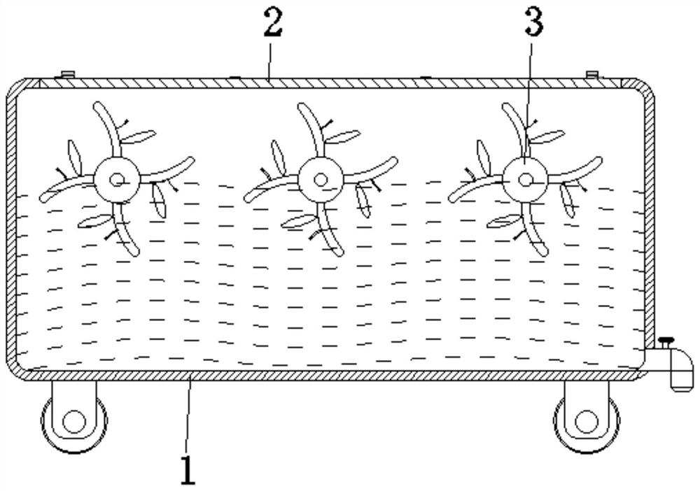
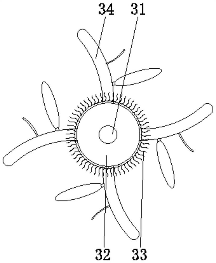
[0034] see Figure 1-8 , the present invention provides a technical solution: a plastic cleaning equipment, including a cleaning box 1, a top cover 2, and a cleaning device 3, the top cover 2 is rotatably connected to the top center of the cleaning box 1, and the cleaning device 3 is rotatably connected to the cleaning box 1 Between the corresponding two sides of the inner wall and close to the top cover 2, the cleaning device 3 is evenly distributed inside the cleaning box 1. The cleaning device 3 is provided with a driving shaft 31, a roller 32, a cleaning brush 33, a scrubbing device 34, and a roller 32 is fixed on the surface central position of driving shaft 31 and is positioned at the inside of cleaning box 1, and cleaning brush 33 is fixed on the surface of cylinder 32, and cleaning brush 33 is evenly distributed on the surface of cylinder 32, and brushing device 34 is fixed on the surface of cylinder 32, can Cleaning sheet plastics floating on the water surface reduces...

Embodiment example 2

[0039] The lever device 346 is provided with a lever body 3461, a channel 3462, a connecting hole 3463, an elastic film 3464, and a brush 3465. The channel 3462 is set at the inner center of the lever body 3461, and one end of the channel 3462 communicates with the elastic airbag 345, and connects The hole 3463 is set inside the lever body 3461 and communicates with the channel 3462. The elastic film 3464 is fixed on the surface of the lever body 3461 and is located in the connection. When the lever body 3461 is moved, the accumulated plastic is in a vertical state. Under the effect of its own buoyancy, it rises rapidly so as to scrub. When the elastic airbag 345 discharges gas into the passage 3462 and the connecting hole 3463, the elastic membrane 3464 is bulged under the influence of pressure, and then the brush 3465 is attached to the rising plastic. Surface, so as to use the rise of the plastic itself for automatic cleaning.

[0040] During use, the sheet-like floating pl...


PUM


Abstract

The invention discloses plastic cleaning equipment comprising a cleaning box, a top cover and cleaning devices, the top cover is rotationally connected to the center of the top of the cleaning box, the cleaning devices are rotationally connected to the positions, close to the top cover, between the two corresponding sides of the inner wall of the cleaning box, and the cleaning devices are evenly distributed in the cleaning box. A roller is fixed to the center of the surface of a driving rotating shaft and located in the cleaning box, cleaning brushes are fixed to the surface of the roller and evenly distributed on the surface of the roller, and a brushing device is fixed to the surface of the roller. According to the plastic cleaning equipment, the purposes of pressing down and cleaning are achieved, flaky floating plastic chips are pressed down to make full contact with water, rise through the buoyancy of the flaky floating plastic chips and are combined with the cleaning equipment for rapid cleaning, smooth completion of cleaning work is facilitated, adaptability is high, limitation is reduced, and the cleaning efficiency and the use performance are improved.

Description

technical field [0001] The invention relates to the technical field of plastic cleaning, in particular to plastic cleaning equipment. Background technique [0002] The main component of plastic is resin. The term resin was originally named after the lipids secreted by animals and plants, such as rosin, shellac, etc. Resin refers to a polymer compound that has not been mixed with various additives. Resin accounts for about 40% to 100% of the total weight of the plastic. The basic properties of plastics are mainly determined by the nature of the resin, but additives also play an important role. Some plastics are basically composed of synthetic resins, with no or few additives, such as plexiglass, polystyrene, etc. Plastic granules are raw materials for storage, transportation and processing of plastics in the form of semi-finished products. With the continuous development of science and technology, the application of plastics is becoming more and more extensive, so there a...

Claims


Application Information

Patent Timeline
Patent Type & Authority Applications(China)
IPC IPC(8): B08B3/10B08B1/04B29B17/00B08B13/00
CPCB08B1/04B08B3/10B08B13/00B29B17/00B29B2017/0015Y02W30/62
Inventor 胡浩
Owner 见才福
Why Eureka
Try Eureka