
Stainless steel cup stamping die

A stamping die and stainless steel technology, applied in the field of stainless steel cup stamping die, can solve the problems of affecting the qualified rate and delicate feeling of stainless steel cups, reducing rod pressure and roller grinding polishing degree, and increasing the loss of shaving and white forming parts.

Inactive Publication Date: 2021-05-18
曾丽琼
View PDF0 Cites 0 Cited by
  • Summary
  • Abstract
  • Description
  • Claims
  • Application Information

AI Technical Summary

Problems solved by technology

[0004] Aiming at the deficiencies in the prior art, the object of the present invention is to provide a stamping die for stainless steel cups to solve the problem that the blanking preparation of stainless steel cups requires stamping and molding, and the inner grinding surface avoids roughness. It will cause the phenomenon of collision, bending and deflection of the inner rods when the double rods are rolled and pressed, resulting in the reduction of the subsequent rod pressure and roller grinding polish, and the phenomenon that the slight angled end cannot be rolled, and the bending of the roller rods cannot be corrected. Operation, resulting in continuous loss of work, the stress shaving and whitening of the frame in the mold increases the loss of formed parts, which affects the pass rate and exquisiteness of stainless steel cups.

Method used


Image

  • Stainless steel cup stamping die
  • Stainless steel cup stamping die
  • Stainless steel cup stamping die

Examples


Embodiment 1

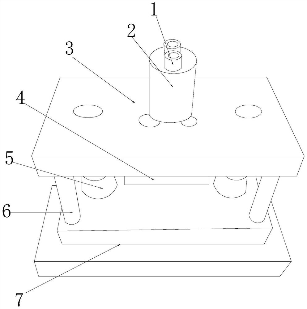
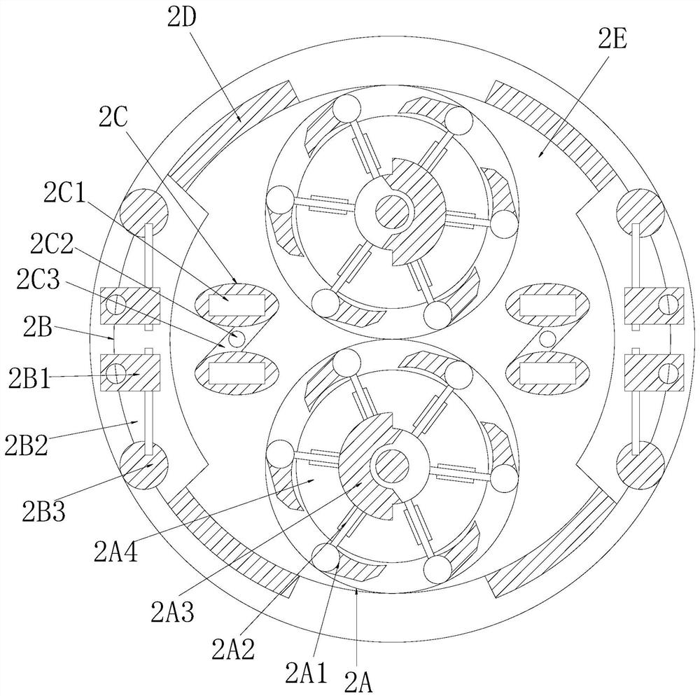
[0032] see Figure 1-Figure 6 , the present invention provides a stainless steel cup stamping die, its structure includes: short cap 1, pressure roller clamp cylinder 2, upper parting panel 3, threaded ring splint 4, clamping wheel seat 5, spring tube 6, base The liner block 7, the pressure roller clamp cylinder 2 is inserted on the top of the upper parting panel 3 and is perpendicular to each other, the short sleeve cap 1 is installed on the top of the pressure roller clamp cylinder 2, the thread The ring splint 4 is closely attached to the bottom surface of the upper parting panel 3 and is on the same level. The clamping wheel seat 5 is provided with two and is respectively attached to the left and right sides of the top surface of the base liner plate 7. The base The liner block 7 is mechanically connected to the upper parting panel 3 through the spring tube 6, and the pressure roller clamp cylinder 2 is provided with a sash paddle roller 2A, a spring core clamp column plat...

Embodiment 2

[0039] see Figure 1-Figure 6 , the present invention provides a stainless steel cup stamping die, other aspects are the same as in Embodiment 1, the difference is:

[0040] see figure 2 The folding pad base 2C is composed of an ellipsoidal frame groove pad 2C1, a torsion shaft wheel 2C2, and a slanted fin plate 2C3. On both sides, the torsion wheel 2C2 is installed inside the slanted fin plate 2C3 and is on the same vertical plane, and presses the slanted fin plate 2C3 through the ellipsoidal frame groove pad 2C1 to form the effect of knuckle cushioning and load-bearing operation.

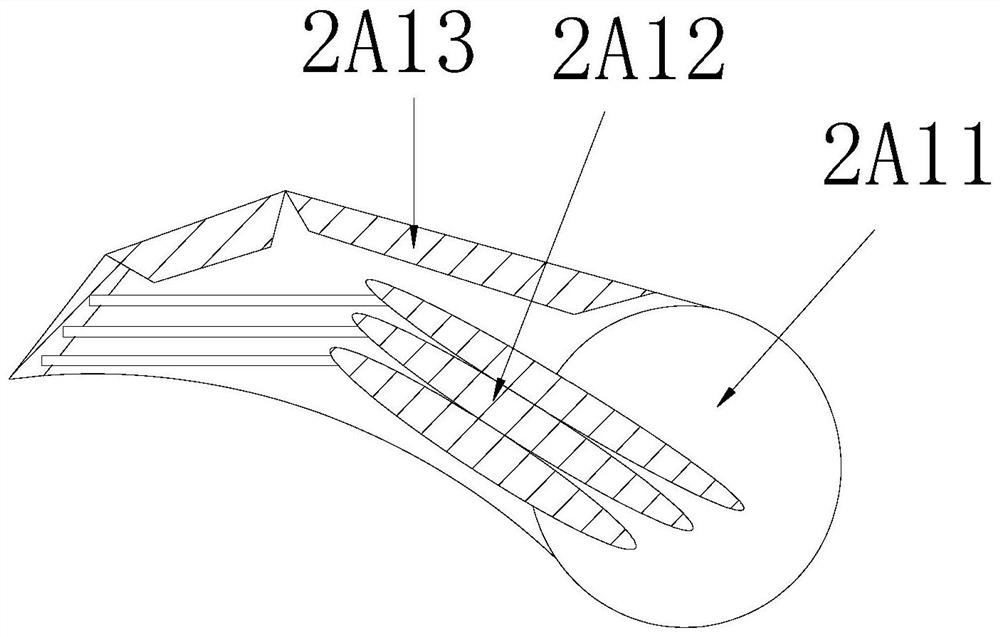
[0041] see Image 6 , the ellipsoidal frame groove pad 2C1 is made up of a cushion ball rod frame 2C11, a double ball strut 2C12, and an ellipsoidal frame groove body 2C13, and the pad ball rod frame 2C11 is installed inside the ellipsoidal frame groove body 2C13, and the There are four double-ball struts 2C12, which are respectively inserted on the left and right sides of the ellipsoidal fram...


PUM


Abstract

The invention discloses a stainless steel cup stamping die which structurally comprises a short sleeve cap, a compression roller forceps holder column casing, an upper parting panel, a threaded ring clamping plate, clamping wheel seats, spring pipes and a base lining plate block. According to the stainless steel cup stamping die, the short sleeve cap and the compression roller forceps holder column casing are in cooperation, the short sleeve cap is matched with a double-station sector plate paddle roller at the top of a stamping die frame cylinder, so that the effects of polishing treatment of a hook claw lug plate and a sector plate wheel core cooperating with a lining cutter for wire drawing and edge planing and wire drawing, lifting and sliding brushing are achieved, it is effectively guaranteed that after rolling, grinding and polishing of the sector plate paddle roller, the trimming operation effect of wrapping and pressing the cambered surface in a ring-surface cup body is achieved through wire drawing of upper and lower correction point positions, the integrated balance structure of stainless steel stamping treatment is improved, the delicacy of follow-up finish machining and grinding treatment lines is promoted, and therefore through the flexibility of mechanical components in a spring core clamp column plate and a folding supporting cushion base maintenance stamping die and the anti-deviation opposite ejection operation effect of rod pieces, the follow-up stainless steel cup batch qualification rate and the smooth feeling of the inner cambered surfaces of cups are improved.

Description

technical field [0001] The invention relates to a stamping die for a stainless steel cup, which belongs to the field of dies. Background technique [0002] The stamping die is used to punch metal blocks to prepare the plastic end of the blow molding mold to effectively ensure the contrast effect of the pressing graphics and texts, and the fine depiction of the lines in the mold to improve the texture and product precision, and to ensure the processing of cups and artworks by the stamping die The degree of optimization, the shortcomings of the current technology to be optimized are: [0003] The blanking preparation of stainless steel cups requires stamping and molding, and the inner grinding surface avoids roughness. Drawing smoothness is required to pull the roller grinding operation, so that the impact of the inner rod collision and bending deflection during the rolling double rods will be caused in the mold, resulting in subsequent rods. The degree of polishing of the pr...

Claims


Application Information

Patent Timeline
Patent Type & Authority Applications(China)
IPC IPC(8): B21D28/14B21D51/18
CPCB21D28/14B21D51/18
Inventor 柳伙林
Owner 曾丽琼
Learn More