Diesel engine tray clamping structure

A diesel engine and pallet technology, applied in metal processing, metal processing equipment, manufacturing tools, etc., can solve problems such as low work efficiency, high safety hazards, and large impact inertia

Pending Publication Date: 2021-05-18
GUANGXI YUCHAI MASCH CO LTD
View PDF0 Cites 0 Cited by
  • Summary
  • Abstract
  • Description
  • Claims
  • Application Information

AI Technical Summary

Problems solved by technology

[0003] The purpose of the present invention is to provide a diesel engine tray clamping structure to solve the problem that the pallet is unstable due to the large impact inertia in the process of tightening the bolts in the prior art, which leads to poor alignment between the tightening equipment and the bolts, and the rework of unqualified diesel engine bodies increases the Workers' labor intensity, low work efficiency and high safety hazards

Method used


Image

  • Diesel engine tray clamping structure
  • Diesel engine tray clamping structure
  • Diesel engine tray clamping structure

Examples


Embodiment Construction

[0024] The following will be described in detail in conjunction with specific embodiments.

[0025] The present invention will be further described in detail below in combination with specific embodiments. It should be emphasized that the following description is only exemplary and not intended to limit the scope of the invention and its application.

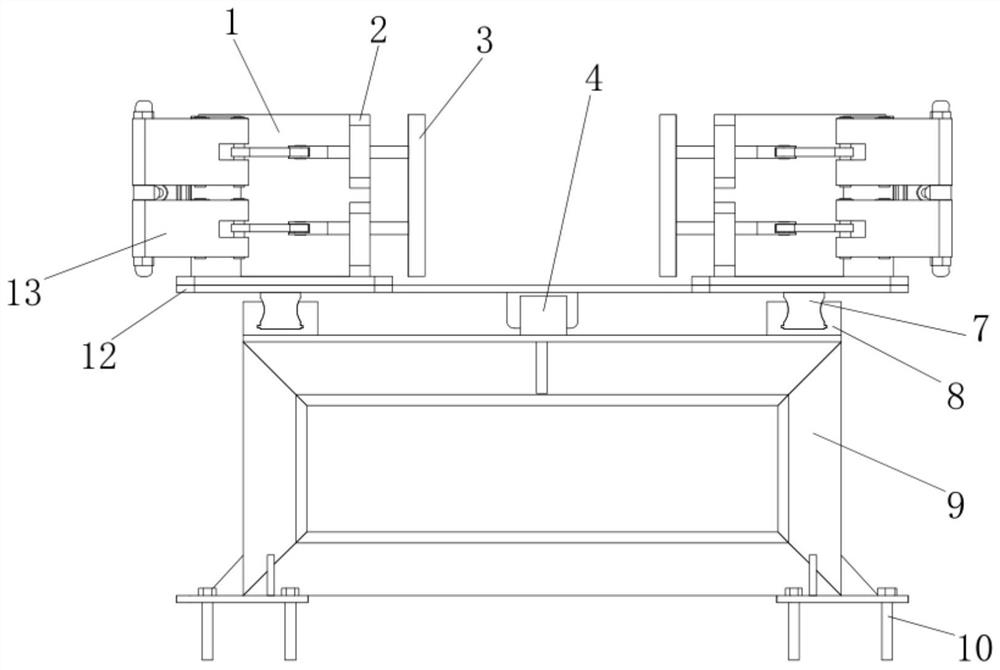
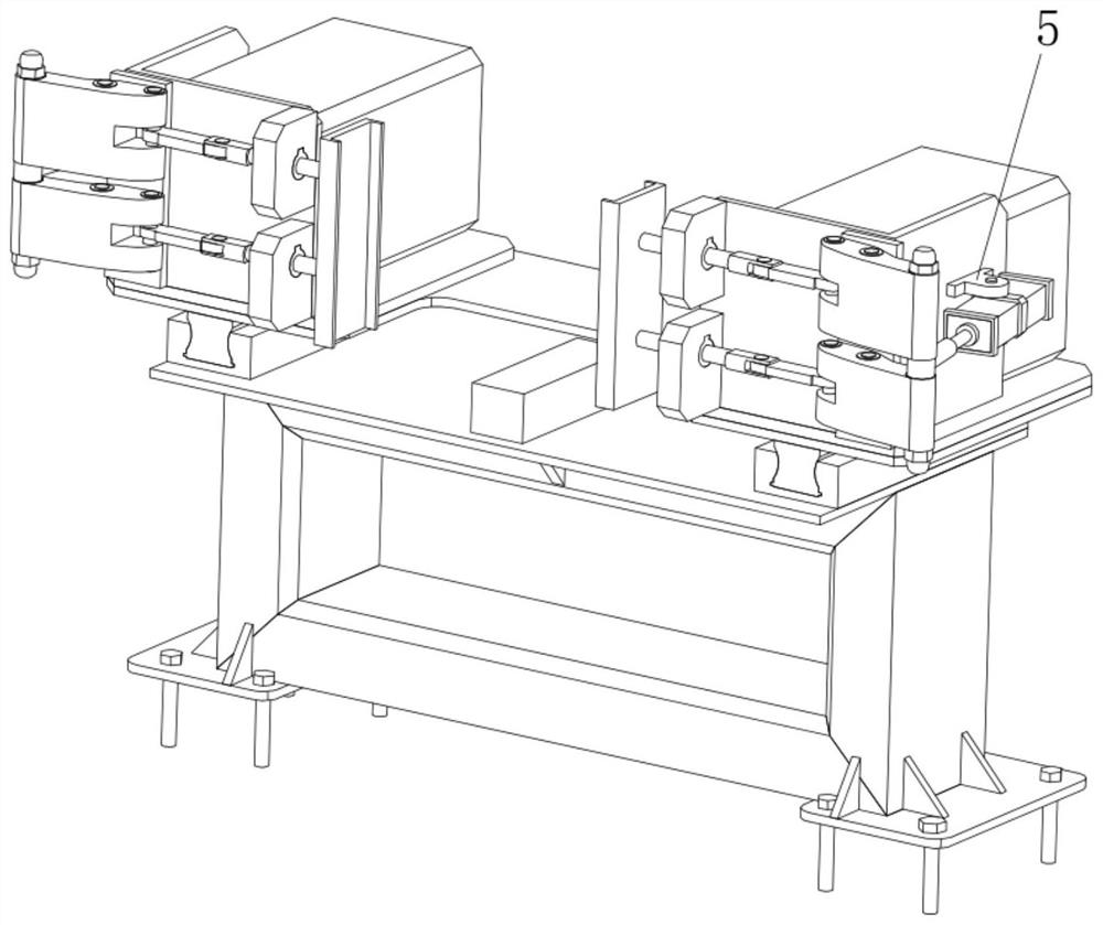
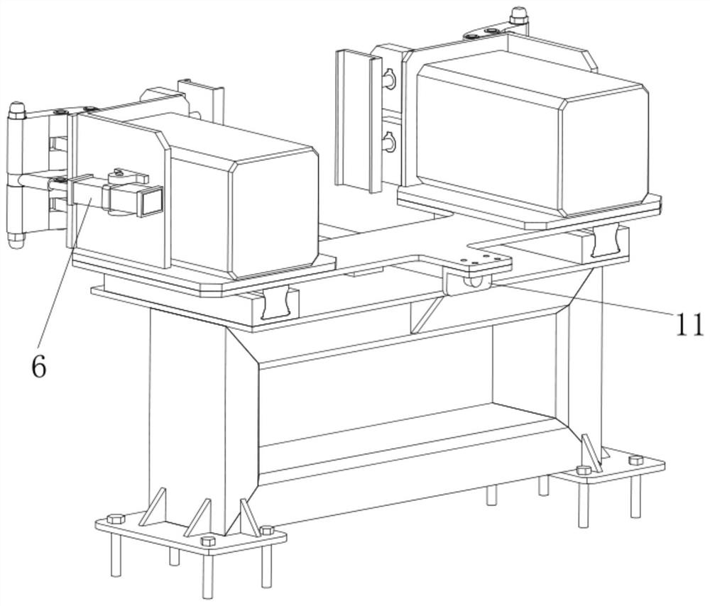
[0026] A diesel engine pallet clamping structure, including a clamping assembly, the clamping assembly is divided into a left clamping assembly and a right clamping assembly, the left clamping assembly is composed of a clamping assembly fixing seat 1, a cylinder 6, an elastic structure 13 and a clamping assembly Claw 3 is formed, and the left end face of clamping assembly fixing seat 1 is provided with cylinder fixing seat 5, and cylinder fixing seat 5 is provided with cylinder 6, and the front of cylinder 6 is provided with elastic structure 13, and elastic structure 13 includes connecting column 13-1 , the middle part of the ...


PUM


Abstract

The invention discloses a diesel engine tray clamping structure which comprises a clamping assembly. The clamping assembly is divided into a left clamping assembly body and a right clamping assembly body. The left clamping assembly body is composed of a clamping assembly fixing base, an air cylinder, a tightening structure and a clamping claw. The tightening structure is arranged in front of the air cylinder, and the tightening structure comprises a connecting column. A rotating hollowed cylinder is arranged on the connecting column, a swing block is arranged on the side portion of the hollowed cylinder, and a groove is formed in the other end of the swing block. A through hole penetrating to the bottom of the groove is formed in the top of the groove, a connecting rod is arranged in the groove, and the clamping claw is arranged at the other end of the connecting rod. The right clamping assembly body and the left clamping assembly body are the same in structure. According to the diesel engine tray clamping structure, the working stability can be ensured, the working alignment performance is improved, and the rejection rate of products is reduced.

Description

【Technical field】 [0001] The invention belongs to the technical field of tray fixing for carrying engine equipment, and in particular relates to a diesel engine tray clamping structure. 【Background technique】 [0002] At present, the diesel engine body is transferred to the cylinder head bolt tightening process on the processing line body roller table. 18 tightening shafts need to tighten the bolts on the cylinder head at the same time. The pallet vibrates greatly, and the pallet shakes unstable during the bolt tightening process. When the pallet shakes and tilts, the alignment of the tightening equipment will deteriorate, which will affect the assembly quality of the diesel engine cylinder head bolts, and frequent rework will lead to high labor intensity for workers. , the work efficiency is low; in severe cases, the collision between the tightening equipment and the diesel engine body will occur due to the poor alignment rate, and the safety hazard is high. Still do not h...

Claims


Application Information

Patent Timeline
IPC IPC(8): B23P19/06
CPCB23P19/006B23P19/069
Inventor 陈太优陈运军
Owner GUANGXI YUCHAI MASCH CO LTD
Why Eureka
Try Eureka