Throttling valve alloy valve body heat treatment system

A technology of heat treatment system and throttle valve, applied in metal processing equipment, manufacturing tools, grinding drive devices, etc., can solve the problems of reducing the efficiency and effect of valve body grinding, reducing the efficiency of valve body grinding mechanical grinding, etc.

Inactive Publication Date: 2021-05-18
周圳慧
View PDF5 Cites 2 Cited by
  • Summary
  • Abstract
  • Description
  • Claims
  • Application Information

AI Technical Summary

Problems solved by technology

[0004] 1. The existing valve body grinding machine usually consumes time in the process of turnover, clamping and disassembly, which reduces the efficiency of the valve body grinding machine for grinding it;
[0005] 2. Existing valve body grinding machines can only be replaced frequently. When the inner wall is polished, the clamping end of the outer clamping mechanism cannot rotate. When the outer wall is polished, the clamping end of the clamping mechanism The end cannot be rotated, which reduces the efficiency and effect of grinding the valve body

Method used


Image

  • Throttling valve alloy valve body heat treatment system
  • Throttling valve alloy valve body heat treatment system
  • Throttling valve alloy valve body heat treatment system

Examples


Embodiment Construction

[0025] In order to make the technical means, creative features, goals and effects achieved by the present invention easy to understand, the present invention will be further described below in conjunction with specific illustrations. It should be noted that, in the case of no conflict, the embodiments in the present application and the features in the embodiments can be combined with each other.

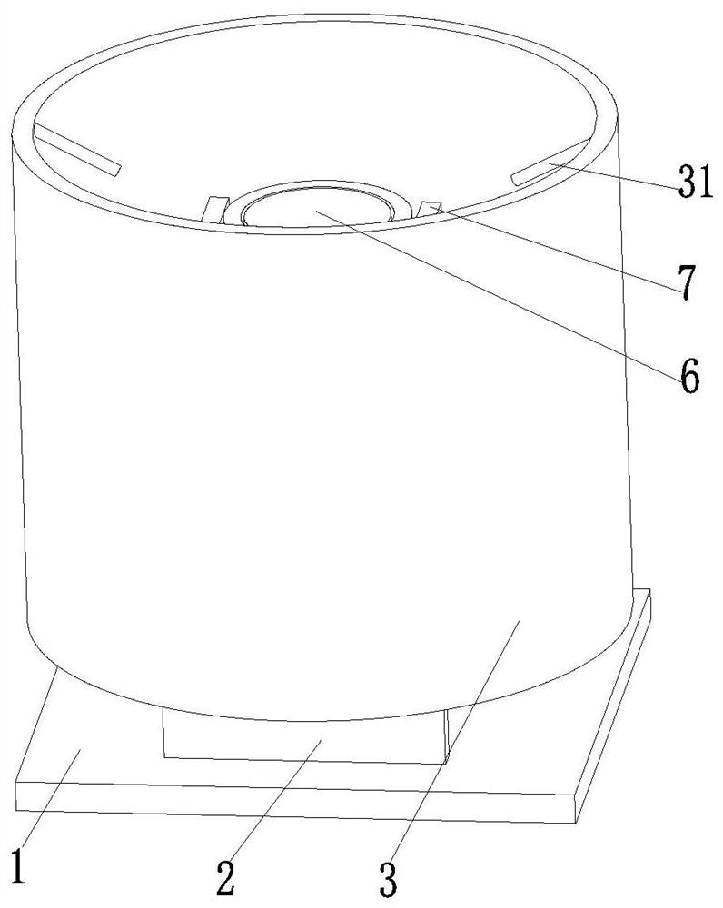
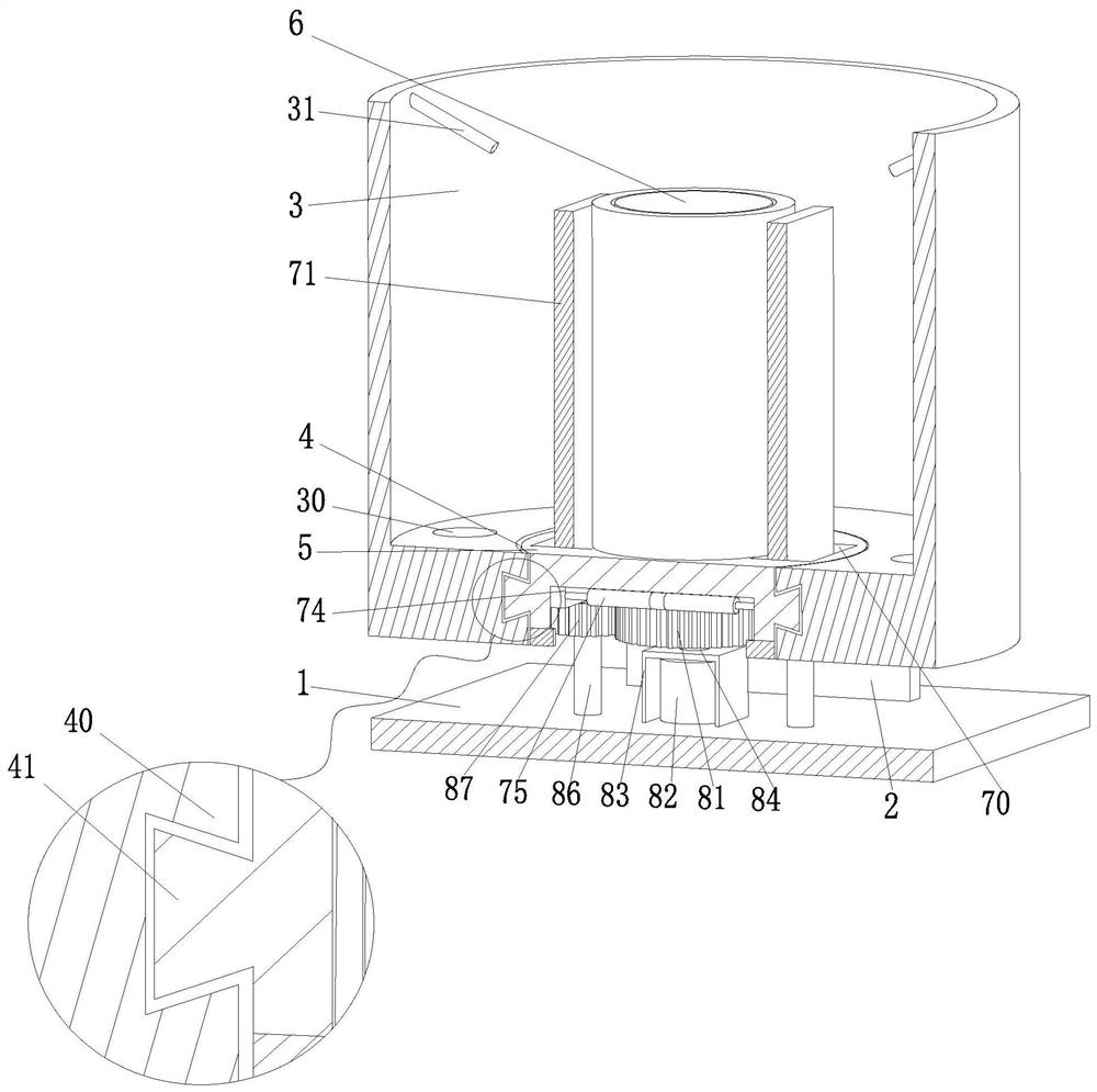
[0026] like Figure 1 to Figure 6 As shown, a throttle valve alloy valve body heat treatment system includes a base 1, a support plate 2, a mounting cylinder 3, a rotating groove 4, a rotating disk 5, an inner clamping mechanism 6, an outer clamping mechanism 7 and a driving mechanism 8, The upper end of the base 1 is provided with a support plate 2 on both sides of the front and back, and the upper end of the support plate 2 is jointly provided with an installation cylinder 3. The installation cylinder 3 is a cylindrical structure with an upper end opening, and the lower end of the ...


PUM


Abstract

The invention relates to a throttling valve alloy valve body heat treatment system. The throttling valve alloy valve body heat treatment system comprises a base, supporting plates, a mounting cylinder, a rotating groove, a rotating disc, an inner clamping mechanism, an outer clamping mechanism and a driving mechanism, the supporting plates are arranged on the front side and the rear side of the upper end face of the base, the mounting cylinder is arranged at the upper ends of the supporting plates, and the mounting cylinder is of a cylindrical structure with the upper end open. The rotating groove is formed in the lower end of the mounting cylinder, the rotating disc is mounted in the rotating groove in a rotating fit mode, a round hole is formed in the middle of the rotating disc, the inner clamping mechanism is arranged in the round hole in a rotating fit mode, the outer clamping mechanism is arranged at the position, located on the outer side of the inner clamping mechanism, of the upper end of the rotating disc, and the inner clamping mechanism is connected with the lower end of the outer clamping mechanism through the driving mechanism. The driving mechanism is installed on the upper end face of the base. The problems that a large amount of time is consumed when an existing machine is turned over, clamped and disassembled, so that the grinding efficiency of the machine is reduced; and in the prior art, machines can only be replaced frequently, and the grinding efficiency of the valve body is reduced are solved.

Description

technical field [0001] The invention relates to the field of throttle valve preparation, in particular to a heat treatment system for a throttle valve alloy valve body. Background technique [0002] A throttle valve is a valve that controls fluid flow by changing the throttle section or throttle length. Throttle valves can be divided into straight-through type and angle type according to the channel mode. Throttle valves usually work within a small opening range and do not require strict sealing when closing. The throttle valve has a simple structure and is easy to Manufacturing and maintenance, low cost and other characteristics, and widely used in society. A general throttle valve is composed of a top cover, a guide sleeve, a valve body, a valve core, an oil port and a bottom cover, and the valve body is divided into cast iron, cast steel, alloy, stainless steel, carbon steel, plastic, copper, etc. , and the valve body is a major part of the valve, and there are differen...

Claims


Application Information

Patent Timeline
Patent Type & Authority Applications(China)
IPC IPC(8): B24B9/04B24B41/02B24B41/06B24B47/12
CPCB24B9/04B24B41/067B24B41/02B24B47/12
Inventor 周圳慧朱轶静
Owner 周圳慧
Why Eureka
Try Eureka