PE plastic thin film preparation method
A plastic film and equipment technology, applied in the field of PE plastic film preparation, can solve the problems of high input cost, residual impurities at the air outlet, adverse effects on the quality of film bubble production, etc.
- Summary
- Abstract
- Description
- Claims
- Application Information
AI Technical Summary
Problems solved by technology
Method used
Image

Examples
Embodiment Construction
[0038] The embodiments of the present invention will be described in detail below with reference to the accompanying drawings, but the present invention can be implemented in many different ways defined and covered by the claims.
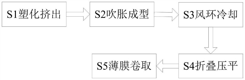
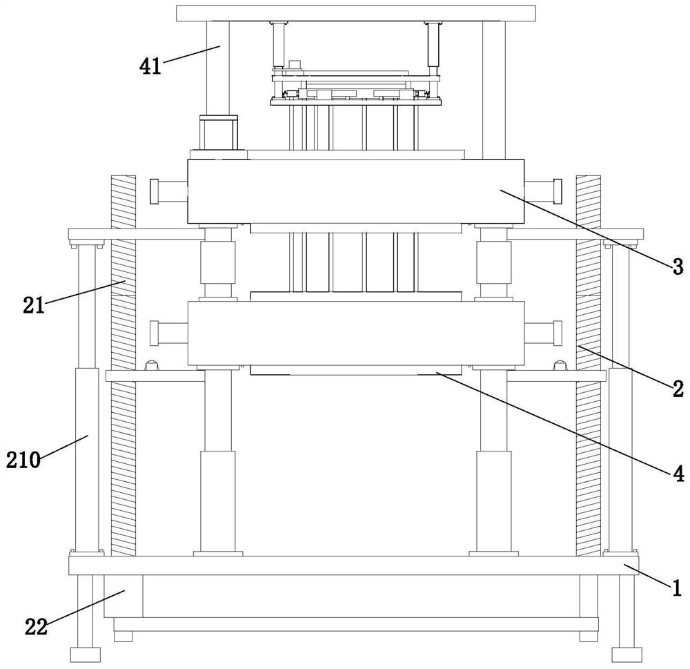
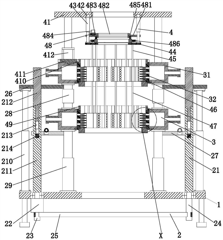
[0039] Such as Figure 1 to Figure 9 As shown, a PE plastic film preparation method uses an air ring cooling device, the air ring cooling device includes a mounting base 1, a lifting device 2, an air ring 3 and a cleaning device 4, and is prepared by using the above air ring cooling device The specific method flow for PE plastic film is as follows:
[0040] S1. Plasticizing extrusion: melt the plastic particles through the extruder and then plasticize them, and extrude a cylindrical pipe ring through the annular gap of the front port die;
[0041] S2. Inflation molding: the compressed air is introduced into the center hole of the mandrel of the machine head, and the pipe ring is blown into a bubble tube shape to obtain a film bubble;
[0042] S3. ...
PUM
 Abstract
Description
Claims
Application Information