Charcoal strip clamping device for art painting and fixing method

A gripper and painting technology, applied in the field of art tools, can solve problems such as the weakening of the gripping effect and the fixed length of the carbon fine strips.

Active Publication Date: 2021-05-18
HEIHE UNIV
View PDF4 Cites 0 Cited by
  • Summary
  • Abstract
  • Description
  • Claims
  • Application Information

AI Technical Summary

Problems solved by technology

[0004] The object of the present invention is to provide a carbon strip holder and fixed method

Method used


Image

  • Charcoal strip clamping device for art painting and fixing method
  • Charcoal strip clamping device for art painting and fixing method
  • Charcoal strip clamping device for art painting and fixing method

Examples


specific Embodiment approach 1

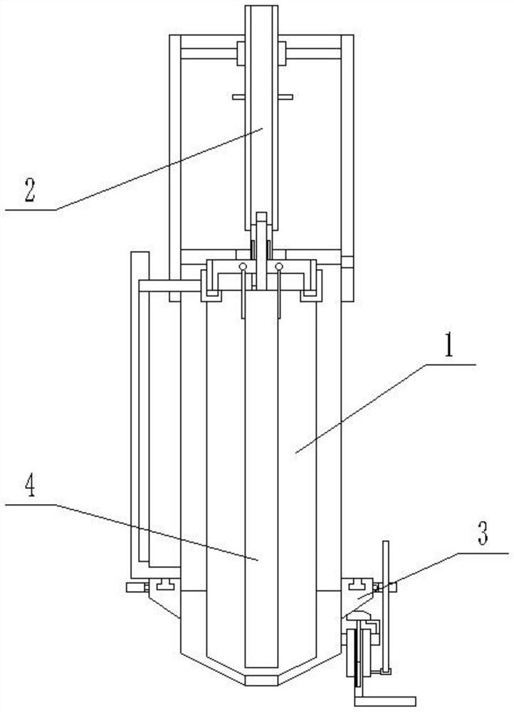
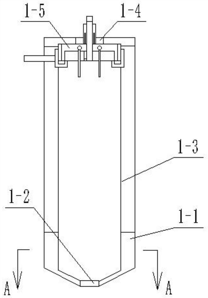
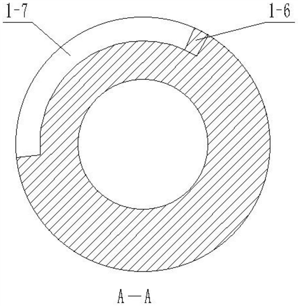
[0033] Specific implementation mode one: as Figure 1-13 As shown, this embodiment describes a carbon strip holder for fine art painting, including a housing 1, a restricting device I2 and a restricting device II3; the housing 1 includes a housing main body 1-1, a clamping device 1-5 and Magnet I1-6; the top of the housing main body 1-1 is provided with a through hole I1-4, the bottom end of the housing main body 1-1 is provided with a through hole II1-2, and the side wall of the housing main body 1-1 is axially provided with Two slideways I1-3; the clamping device 1-5 is arranged inside the housing main body 1-1, and the clamping device 1-5 is slidingly matched with the slideway I1-3; the outer wall of the housing main body 1-1 An arc-shaped groove I1-7 coaxial with the housing main body 1-1 is provided near the bottom end; the magnet I1-6 is fixedly connected to one end of the arc-shaped groove I1-7;

[0034] The clamping device 1-5 includes a cover 1-5-1, a threaded cylind...

specific Embodiment approach 2

[0042] Specific implementation mode two: as Figure 1-13 As shown, this embodiment is a further description of Embodiment 1. When the screw rod 1-5-10 cooperates with the thread on the inner wall of the rectangular cylinder I1-5-9, the insert at the lower end of the rectangular cylinder I1-5-9 Groove breaks away from limit bar 1-5-11. When the rectangular cylinder I1-5-9 rotates with the rectangular cylinder II2-4, it does not drive the limit rod 1-5-11 to rotate, and then does not drive the cover 1-5-1 to rotate, so as to avoid affecting the clamping of the clamping device 1-5. hold the effect.

specific Embodiment approach 3

[0043] Specific implementation mode three: as Figure 1-13 As shown, this embodiment is a further description of Embodiment 1, and the arc center angle corresponding to the arc-shaped groove I1-7 is less than or equal to 30°. Ensure the distance between the magnet Ⅰ1-6 and the magnet Ⅱ3-5, avoid the length of the arc groove Ⅰ1-7 being too long, when the magnet Ⅰ1-6 and the magnet Ⅱ3-5 repel, the magnet Ⅱ3-5 collides with the arc groove Ⅰ1-7 The edge reduces the risk of the magnet II 3-5 falling and affects the service life of the magnet II 3-5.


PUM


Abstract

The invention discloses a charcoal strip clamping device for art painting and a fixing method, and belongs to the field of art tools. A sliding rod is in sliding fit with a spiral groove and a limiting groove II. A length control device is fixedly connected to the side face of a shell body. A control circular ring is connected to the outer side of the shell body through a bearing. A magnet II is in sliding fit with an arc-shaped groove I, and when a magnet II is close to the magnet I, the magnet II and the magnet I repel each other. A rectangular cylinder II is in interference fit with a rectangular cylinder I. A charcoal strip is fixed through the shell body and a clamping device body, no spring is arranged, and the situation that the service life is shortened due to long-time compression of the spring, and then the clamping effect of the clamping device body is affected is avoided; and in addition, the length of the portion, extending out of a shell, of the charcoal strip can be adjusted according to habits of a user, the situation that the extending length of the charcoal strip is too long or too short, the user needs to adjust the length with hands, fingers of the user are polluted, time is wasted is avoided, and the charcoal strips of different sizes can be clamped.

Description

technical field [0001] The invention relates to a carbon strip holder for art painting and a fixing method, belonging to the field of art utensils. Background technique [0002] Carbon strips, also known as carbon lead cores, are specially used for drawing and sketching. In addition to requiring a certain strength and hardness, they also need to have a sense of carbon. Carbon fine strips are made of charcoal powder, carbon black powder and clay, and the process is basically the same as graphite clay lead cores, but does not require oil immersion treatment. Carbon strips can have various colors after adding other colored materials. [0003] The patent number is 201821115683.5, and the patent name is a public utility model patent for a carbon strip painting holder for arts and crafts, which records that the device includes a holding tube, a spring, a push-pull, a supporter, a driving piece, and a clip , through the push-pull combined with the spring structure, use the elasti...

Claims


Application Information

Patent Timeline
IPC IPC(8): B44D3/22
CPCB44D3/225
Inventor 胡博迟慧鑫解辉张潇徐萌李凡陈宪浩夏静怡徐瑶瑜雪
Owner HEIHE UNIV
Why Eureka
Try Eureka