Feed equipment for conveying and clamping short strips

A feeding equipment and material clamping technology, applied in mechanical equipment, metal processing equipment, feeding devices, etc., can solve problems affecting the normal operation of equipment, equipment damage, parts falling off, etc., to reduce labor intensity and labor costs, reduce Vibration, the effect of improving stamping efficiency

Inactive Publication Date: 2021-05-07
HANGZHOU KINGNET ELECTROMECHANICAL
View PDF7 Cites 0 Cited by
  • Summary
  • Abstract
  • Description
  • Claims
  • Application Information

AI Technical Summary

Problems solved by technology

[0003] At present, in the process of processing high-quality steel, most of them use manual feeding; at present, some manufacturers use mechanical equipment to transport materials when stamping high-quality steel, but because mechanical equipment is used to transport materials, but When the material is stamped, it has a large impact force, so the vibration is relatively large, and the vibration on the material will be transmitted to the equipment, causing the equipment to be subjected to vibration for a long time, resulting in equipment damage and parts falling off, etc. normal operation of the equipment

Method used


Image

  • Feed equipment for conveying and clamping short strips
  • Feed equipment for conveying and clamping short strips
  • Feed equipment for conveying and clamping short strips

Examples


Embodiment 1

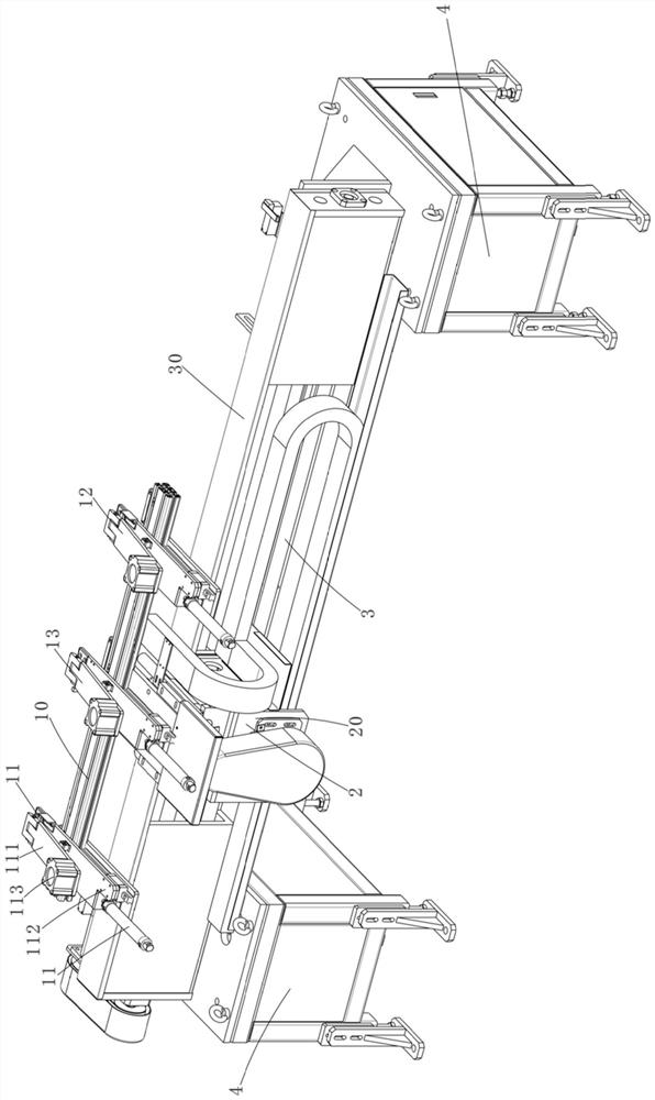
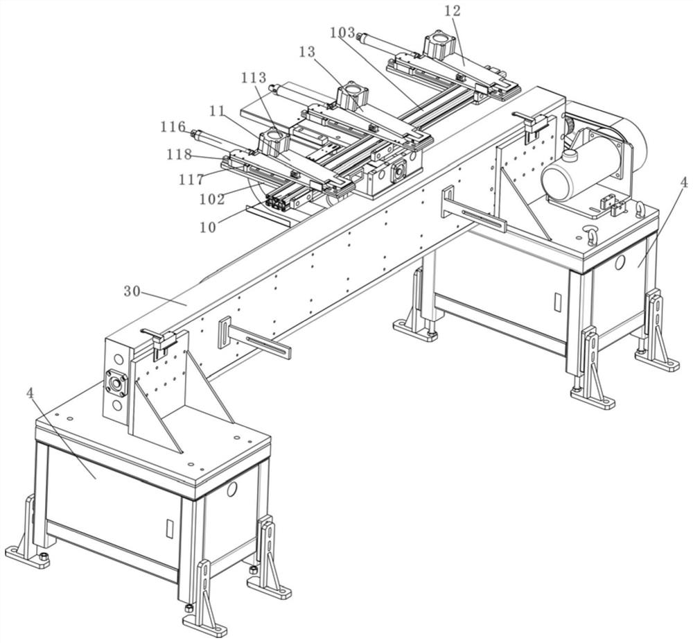
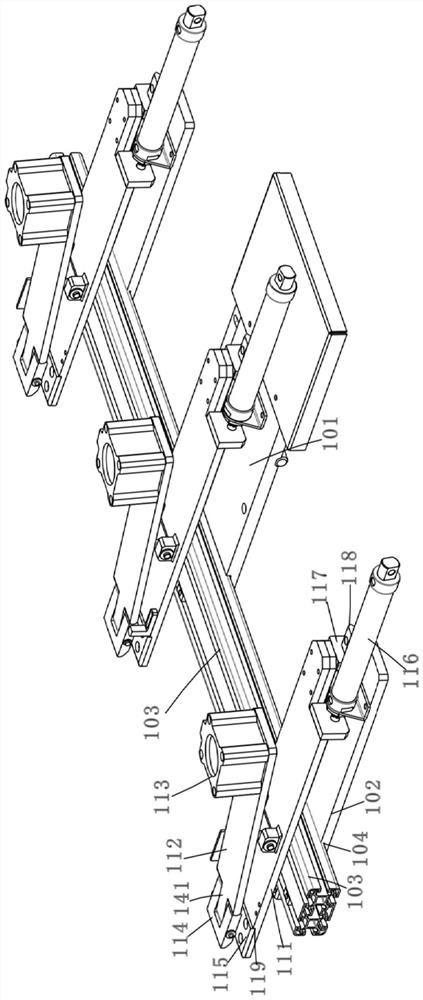
[0041] Such as Figure 1-13As shown, a feeding device for conveying and clamping short strips includes a first frame body 10, a first clamping device 11, a second clamping device 12, a third clamping device 13, and a first driving device 2 and the second driving device 3, wherein the above-mentioned first frame body 10 includes a first support plate 101 arranged horizontally, two second support plates 102 arranged horizontally and a support profile vertically connected to the first and second support plates 103, wherein the above-mentioned first and second support plates are metal plates, and the length of the first and second support plates is the same, the difference is that the width of the first support plate 101 is wider than the width of the above-mentioned second support plate 102; the above-mentioned The first support plate 101 is located in the middle of the two second support plates 102, and a groove 104 is provided at the front ends of the first and second support p...

Embodiment 2

[0053] Such as Figure 14-17As shown, the difference between this embodiment and Embodiment 1 is that this embodiment discloses a shock absorbing device 5 for absorbing vibrations on the second driving device, specifically: the shock absorbing device 5 includes a cylinder body 51, a cavity 52. Hydraulic oil and damping piston 53, the cylinder 51 is a metal cylinder, the cavity 52 is a cylindrical cavity formed on the cylinder 51, and the hydraulic oil is filled in the cavity 52; The damping piston 53 includes a rod body 531 and an elastic sealing block 532. The rod body 531 is a metal column, and the elastic sealing block 532 is a cylindrical rubber block. There are two positioning rings on the side wall of the elastic sealing block 532. Concave ring 533, a sealing ring 534 is sleeved in each ring of positioning concave ring 533, and the sealing ring 534 is a rubber ring. When the damping piston 53 is inserted into the cavity 52, the sealing ring 534 is in close contact with ...


PUM


Abstract

The invention discloses a feeding device for conveying and clamping short strips, which comprises a first frame body; a first material clamping device for clamping one end of the material; a second material clamping device and the first clamping device The material device cooperates to clamp the other end of the material; the third material clamping device is arranged between the first and second material clamping devices, and is used to clamp the middle part of the material, when the third material clamping device clamps the material In the middle, the first or second clamping device releases the material and moves backward. The invention improves the utilization rate of the whole material, reduces the amount of material waste, and reduces the production cost under the same output; realizes fully automatic material feeding, avoids manual movement or flipping of materials during the stamping process, and reduces workers' labor. Reduce labor intensity and labor cost, improve the stamping efficiency of the punch press on the material, that is, increase the production efficiency.

Description

technical field [0001] The invention belongs to the technical field of material transportation, and in particular relates to a feeding device for conveying and clamping short strips. Background technique [0002] In the existing steel industry, steel is roughly divided into two types, one is ordinary steel that is often used in the construction industry in our lives, and the other is high-quality steel that is used to produce blades and chains. The carbon content is low and the hardness is high. Due to the limitation of the process during production, the general width of high-quality steel is limited to within 350mm, and its width is narrow. In the process of using high-quality steel, it uses punching equipment to The steel is stamped. The stamping process is to stamp the steel onto the mold with a punch to form the desired shape. [0003] At present, in the process of processing high-quality steel, most of them use manual feeding; at present, some manufacturers use mechani...

Claims


Application Information

Patent Timeline
Patent Type & Authority Patents(China)
IPC IPC(8): B21D43/02B21D43/00B30B15/04B21D43/20F16F15/027F16F15/04
CPCB21D43/003B21D43/027B21D43/20B30B15/04F16F15/027F16F15/04F16F2238/026
Inventor 潘斌超
Owner HANGZHOU KINGNET ELECTROMECHANICAL
Why Eureka
Try Eureka