
High-pier-side cast-in-place bracket

A high-pier, cast-in-place technology, applied in the erection/assembly of bridges, bridge parts, bridges, etc., can solve the problems of large impact on the appearance quality of concrete, large impact on the construction of the pier body, and adverse effects on concrete.

Pending Publication Date: 2021-05-18
CHINA HYDROELECTRIC ENGINEERING CONSULTING GROUP CHENGDU RESEARCH HYDROELECTRIC INVESTIGATION DESIGN AND INSTITUTE
View PDF0 Cites 0 Cited by
  • Summary
  • Abstract
  • Description
  • Claims
  • Application Information

AI Technical Summary

Problems solved by technology

There are some disadvantages in the above two methods: 1. It is difficult to install and remove
At present, the brackets next to the piers need to be embedded with steel plates or section steel, and welding connections are required during installation, which takes a long time to construct and requires a lot of high-altitude operations; gas cutting is required for removal, and there are also safety risks;
[0003] 2. The bracket structure adopts welding, and the material reuse rate is not high, which is uneconomical;
[0004] 3. Great impact on pier construction
The pier body is densely covered with steel bars, so it is inevitable to cut off the main bars of the pier body, and to embed the entire section steel, the formwork needs to be destroyed, which causes construction inconvenience;
[0005] 4. Pre-embedded steel plates, whole section steel or reserved large notches, welding or cutting will have adverse effects on concrete, especially on the appearance quality of concrete;

Method used


Image

  • High-pier-side cast-in-place bracket
  • High-pier-side cast-in-place bracket
  • High-pier-side cast-in-place bracket

Examples


Embodiment

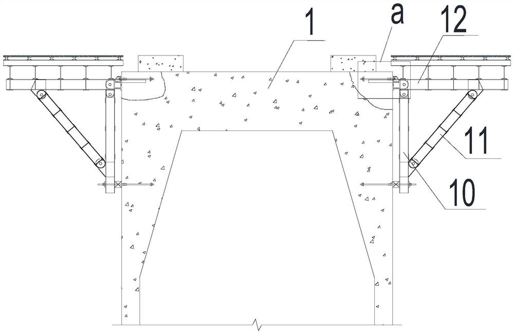
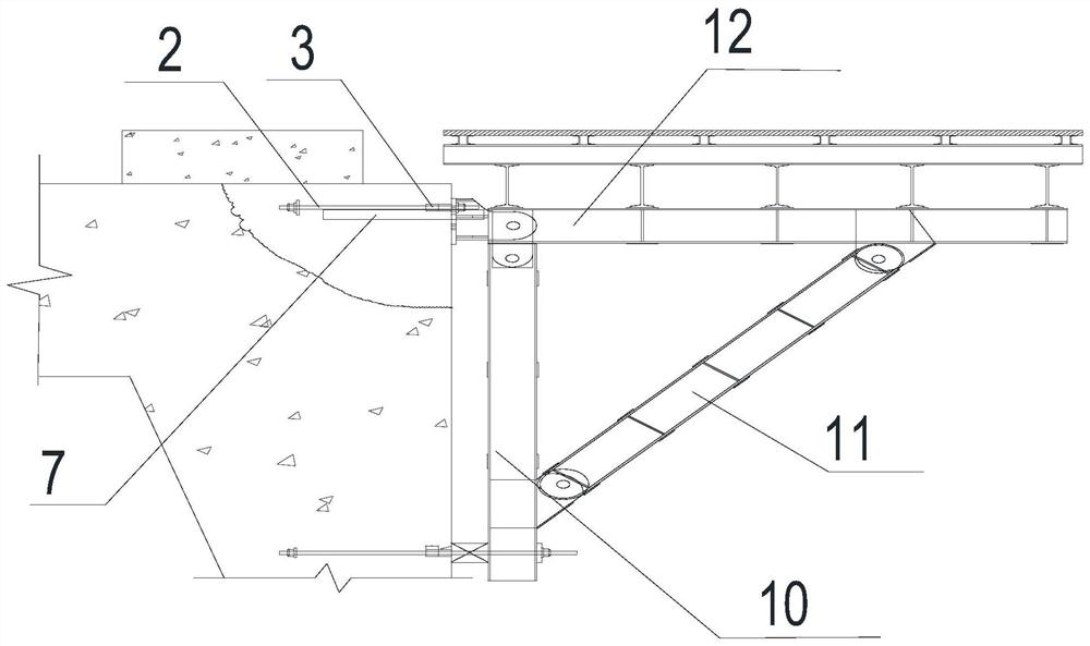
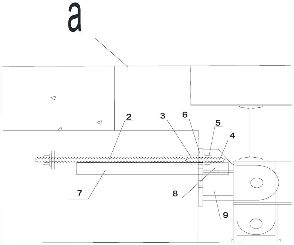
[0040] Example: such as Figure 1 to Figure 7 As shown, a cast-in-place bracket next to a high pier includes support structures respectively arranged on both sides of the pier 1, the support structure is used to support the box girder, and also includes a pre-embedded unit, a backing plate 6 and an accessory hanger 9 ;

[0041] The pre-embedded unit includes a finished-rolled rebar 2, a rebar connector 3 and an anchor bar 4, and the tops of both sides of the pier 1 are provided with a finished-rolled rebar 2 and a rebar connector 3, and the finished-rolled rebar 2 and the rebar connector 3 are located inside the pier 1, the end of the finished rolled rebar 2 away from the center of the pier 1 is connected to one end of the rebar connector 3, and one end of the anchor rib 4 is inserted into the other end of the rebar connector 3 , and connected with the finish-rolled rebar 2, the other end of the anchor bar 4 is located outside the pier 1, and the pre-embedded unit is placed h...


PUM


Abstract

The invention provides a high-pier-side cast-in-place bracket which comprises supporting structures arranged on the two sides of a pier correspondingly and used for supporting box girders and further comprises a pre-embedded unit, a base plate and an accessory hanging base. The pre-embedded unit comprises finish-rolled deformed steel bars, deformed steel bar connectors and anchoring ribs, the finish-rolled deformed steel bars and the deformed steel bar connectors are arranged at the tops of the two sides of the pier and located in the pier, and the ends, away from the center of the pier, of the finish-rolled deformed steel bars are connected with one ends of the deformed steel bar connectors; one end of the anchoring rib is inserted into the other end of the deformed steel bar connector and connected with the finish-rolled deformed steel bar, and the other end of the anchoring rib is located outside the pier; thepre-embedded unit is placed horizontally; the base plate is tightly attached to the outer side of the pier; and the accessory hanging base is fixedly connected with the outer side of the base plate and is used for connecting a supporting structure. According to the scheme, only the steel bars are embedded in the two sides of the pier and do not need to penetrate through the pier, the influence on a pier body and the appearance is small, construction is convenient, and operation time is shortened.

Description

technical field [0001] The invention relates to the field of construction engineering, in particular to a cast-in-place bracket next to a high pier. Background technique [0002] Continuous rigid frame bridges with high piers and continuous girder bridges with high piers are currently the most widely used bridge structures. They have the characteristics of low cost, mature construction technology, and low maintenance costs. In the design of the superstructure box girder of the continuous rigid frame bridge with high piers, the length of the girder blocks is larger than that of the top of the pier. Generally, each end hangs out by about 2 to 4 meters, and cantilever cast-in-place construction is required. Due to the high pier of the bridge pier is relatively large, it can only be used to set the attachment bracket on the top of the pier, and set the distribution beam, bottom formwork and side formwork formwork support on the bracket, and then carry out steel and concrete cons...

Claims


Application Information

Patent Timeline
Patent Type & Authority Applications(China)
IPC IPC(8): E01D21/00E01D19/02
CPCE01D19/02E01D21/00
Inventor 艾明国王扬赵占超张彩楼柏山
Owner CHINA HYDROELECTRIC ENGINEERING CONSULTING GROUP CHENGDU RESEARCH HYDROELECTRIC INVESTIGATION DESIGN AND INSTITUTE
Learn More