
Laser welding control equipment integrating bus stepping drive and control

A technology of laser welding and control equipment, applied in digital control, program control, electrical program control, etc., which can solve the problems of multiple lines, inconvenient installation and disassembly, and large floor space

Pending Publication Date: 2021-05-18
新代科技(苏州)有限公司
View PDF8 Cites 0 Cited by
  • Summary
  • Abstract
  • Description
  • Claims
  • Application Information

AI Technical Summary

Problems solved by technology

However, the disadvantage of laser welding technology compared with the previous welding technology is that special laser welding equipment is rarely seen at present, and they all use multiple related equipment, such as PCs, numerical control cards, stepping motors, relays, valves and The laser welding mechanism composed of interconnection of laser emitting head and other equipment
In this type of laser welding mechanism, a distributed control method of one laser welding controller plus multiple servo drivers is generally adopted. Each device is generally installed independently and connected to each other through cables to form a network in distribution. The degree of integration is low, it occupies a large area, and there are many and complicated lines, which not only increases the cost of the equipment, but also is inconvenient to install and disassemble, and is also easily disturbed by the external environment, which affects the welding work.

Method used


Image

  • Laser welding control equipment integrating bus stepping drive and control

Examples


Embodiment Construction

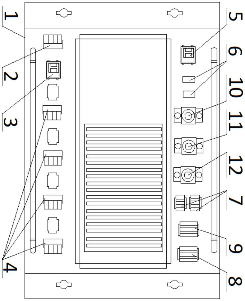
[0017] figure 1 It schematically shows the structure of the wiring surface of a laser welding control device integrated with bus stepping drive and control according to an embodiment of the present invention. Such as figure 1 As shown, the laser welding control equipment includes a shell 1, and a driver and a controller are installed inside the shell 1, and the EtherCAT bus communication protocol is adopted between the driver and the controller, and a laser control module is also arranged on the controller And IO input and output modules.

[0018] Because in laser welding technology, the driver and controller can basically be connected with other equipment, therefore, when the driver and controller are integrated together, other equipment can be directly connected with the laser welding control equipment , to achieve laser welding work together.

[0019] Among them, the equipment directly connected with the laser welding control equipment mainly includes power supply, vario...


PUM


Abstract

The invention discloses laser welding control equipment integrating bus stepping drive and control. According to the equipment, a driver and a controller are installed in a shell and can be connected with a relay, a contactor and a plurality of stepping motors, an EtherCAT bus communication protocol is adopted between the driver and the controller, and a laser control module and an IO input and output module are arranged on the controller. According to the bus stepping drive and control integrated laser welding control equipment, the welding controller and the motor driver are integrated into a whole and connected with other equipment in a welding mechanism, the communication speed is high, external wiring is reduced, and the use cost is reduced. And the anti-interference capability and the stability of the equipment are greatly improved.

Description

technical field [0001] The invention relates to the field of laser welding equipment, in particular to a laser welding control equipment integrating bus stepping drive and control. Background technique [0002] At present, laser welding technology is emerging as a mainstream welding technology, which has a tendency to gradually replace welding technologies such as electric soldering irons. However, the disadvantage of laser welding technology compared with the previous welding technology is that special laser welding equipment is rarely seen at present, and they all use multiple related equipment, such as PCs, numerical control cards, stepping motors, relays, valves and A laser welding mechanism composed of interconnected devices such as laser emitting heads. In this type of laser welding mechanism, a distributed control method of one laser welding controller plus multiple servo drivers is generally adopted. Each device is generally installed independently and connected to ...

Claims


Application Information

Patent Timeline
IPC IPC(8): G05B19/414
CPCG05B19/4142G05B2219/34013
Inventor 唐元克陈信宇李鹏举陆康帆钱厚达李伟阮海涛徐银丽
Owner 新代科技(苏州)有限公司
Learn More