An outdoor power distribution cabinet
A power distribution cabinet, outdoor technology, applied in the substation/distribution device shell, electrical components, substation/switch layout details, etc., can solve the problem of normal use of internal components of the power distribution cabinet, increase the energy consumption and structural cost of the power distribution cabinet , The power distribution cabinet cannot make full use of wind power and other problems to achieve the effect of improving the air compression effect, ensuring sustainable use, and improving the filtering effect.
- Summary
- Abstract
- Description
- Claims
- Application Information
AI Technical Summary
Problems solved by technology
Method used
Image
Examples
Embodiment 1
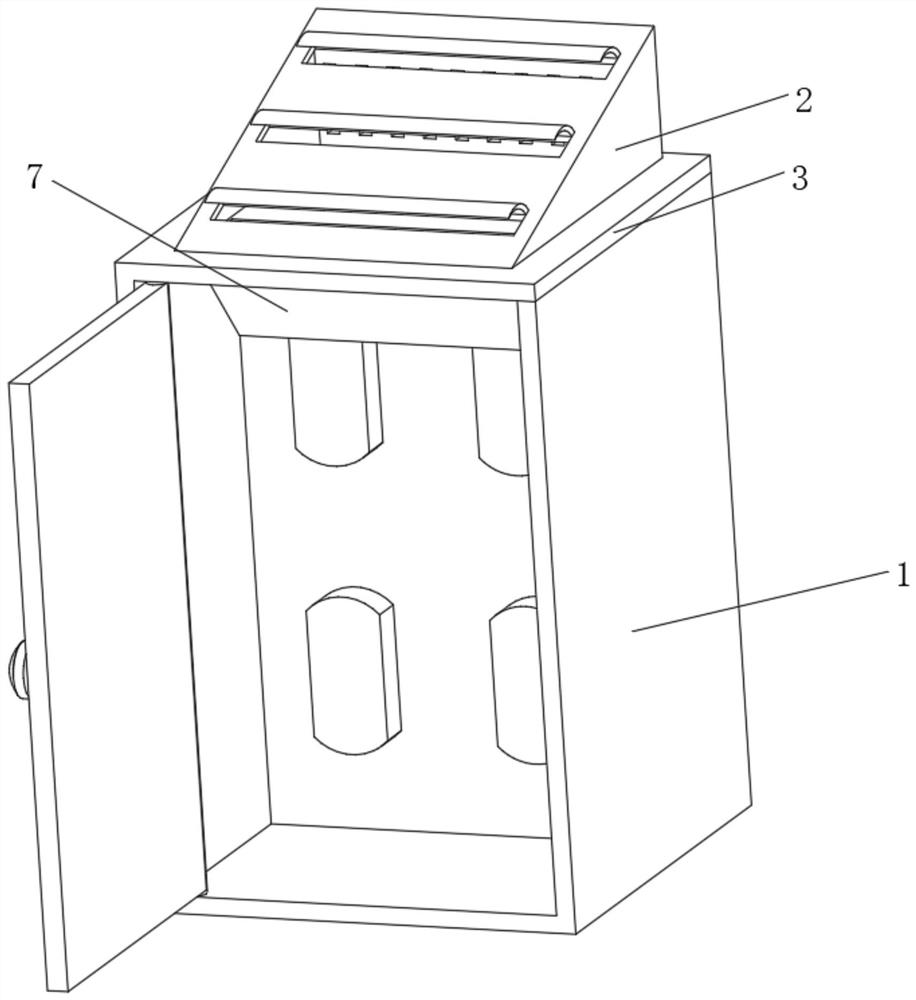
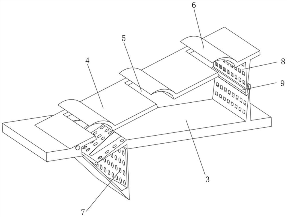
[0033] like Figure 1-2 As shown, the present invention provides a technical solution: an outdoor power distribution cabinet, comprising a cabinet body 1, the top of the cabinet body 1 is fixedly connected with an air induction and heat dissipation mechanism 2, and the air induction heat dissipation mechanism 2 includes a protective top plate 3, and the protective top plate 3 It is fixedly connected with the top of the cabinet 1, and the left side of the top of the protective top plate 3 is rotatably connected with a guiding inclined plate 4. The surface of the top of the guiding inclined plate 4 is evenly provided with ventilation strip holes 5. The top of the guiding inclined plate 4 is located in the ventilation strip hole 5. The position of the right side is fixedly connected with the blocking arc plate 6, the top of the protective top plate 3 and the left side close to the lower part of the guiding inclined plate 4 is fixedly connected with the inner conducting component 7...
Embodiment 2
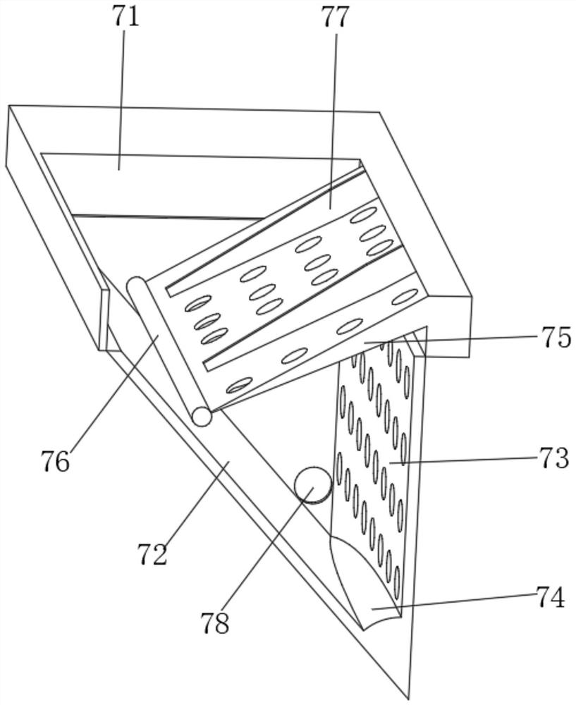
[0035] like image 3 As shown, on the basis of the first embodiment, the present invention provides a technical solution: an outdoor power distribution cabinet, the inner conducting component 7 includes a conducting inner groove 71, and the conducting inner groove 71 is arranged on the left side of the protective top plate 3. Inside, a liquid blocking swash plate 72 is fixedly connected to the left inner wall of the inner groove 71 and is close to the lower position, and an inner ventilation sieve plate 73 is fixedly connected to the right inner wall of the inner groove 71 and is close to the lower position. The bottom of 73 is fixedly connected with the bottom of the liquid blocking swash plate 72 . Achieve precise ventilation and heat dissipation of components inside the power distribution cabinet.
[0036] A shunt arc plate 74 is fixedly connected at the connection between the inner ventilation sieve plate 73 and the liquid blocking inclined plate 72 , and a guide filter p...
Embodiment 3
[0039] like Figure 4-5 As shown, on the basis of Embodiment 1 and Embodiment 2, the present invention provides a technical solution: an outdoor power distribution cabinet, the swing cleaning assembly 9 includes a limiting sealing rod 91, the top of the limiting sealing rod 91 and the filter screen The net 8 is fixedly connected, and the bottom end inside the restricting sealing rod 91 penetrates and is slidably connected with a discharge contacting ball rod 92 , and one end of the discharging contacting ball rod 92 inside the restricting sealing rod 91 is fixedly connected with a rubber stopper plate 93 .
[0040] Limiting baffles 94 are fixedly connected to both sides of the inner top of the limiting sealing rod 91 , and resistance-increasing sealing blocks 95 are fixedly connected to both sides outside the rubber stopper plate 93 . .
[0041] A conduction plug 96 is fixedly connected to the middle position of the inner top end of the limiting sealing rod 91. The conduction...
PUM
 Abstract
Description
Claims
Application Information
 - R&D
- Intellectual Property
- Life Sciences
- Materials
- Tech Scout
- Unparalleled Data Quality
- Higher Quality Content
- 60% Fewer Hallucinations
Browse by: Latest US Patents, China's latest patents, Technical Efficacy Thesaurus, Application Domain, Technology Topic, Popular Technical Reports.
© 2025 PatSnap. All rights reserved.Legal|Privacy policy|Modern Slavery Act Transparency Statement|Sitemap|About US| Contact US: help@patsnap.com


