Forward feedback type absorption circuit for improving efficiency of direct-current solid-state circuit breaker

A solid-state circuit breaker and absorption circuit technology, applied in the field of power electronics, can solve the problems of circuit breaker heating, insulation manufacturing difficulties, reduced service life, etc., and achieve the effect of maintaining normal working life, preventing serious heating, and ensuring normal work.

Active Publication Date: 2021-05-18
NANJING UNIV OF AERONAUTICS & ASTRONAUTICS +1
View PDF6 Cites 0 Cited by
  • Summary
  • Abstract
  • Description
  • Claims
  • Application Information

AI Technical Summary

Problems solved by technology

[0003] The existing ordinary RCD absorbing circuit or MOV absorbing circuit has relatively poor absorbing effect, and cannot realize effective utilization of energy
In practical application, if the ordinary absorbing circuit is used directly, the circuit breaker will heat up seriously, the service life will be greatly reduced, and it will be difficult to make insulation
[0004] At present, many methods have been proposed for the optimization of the absorption circuit of DC solid-state circuit breakers in the literature, and their designs are all about voltage spike suppression, which does not reflect the improvement of efficiency.

Method used


Image

  • Forward feedback type absorption circuit for improving efficiency of direct-current solid-state circuit breaker
  • Forward feedback type absorption circuit for improving efficiency of direct-current solid-state circuit breaker
  • Forward feedback type absorption circuit for improving efficiency of direct-current solid-state circuit breaker

Examples


Embodiment Construction

[0026] The specific embodiments of the present invention will be further described below in conjunction with the accompanying drawings.

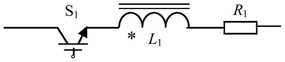
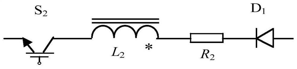
[0027] to combine Figure 1-5 As shown, the present application discloses a forward feedback snubber circuit for improving the efficiency of a DC solid-state circuit breaker, including first main power transistors Q connected in parallel in reverse series 1 and the second main power tube Q 2 The voltage peak absorption circuit at both ends, the forward energy storage circuit, the reverse energy storage circuit and the energy feedback circuit connected in parallel at both ends of the power supply, the first main power tube Q 1 The first end and the second main power tube Q 2 The second end of the connected to the power supply U DC Both ends, the load LOAD end is connected to the second main power tube Q 2 The second end and the other end are connected to the power supply U DC negative electrode.

[0028] to combine figure 1 , Figure ...


PUM


Abstract

The invention discloses a forward feedback type absorption circuit for improving the efficiency of a direct-current solid-state circuit breaker, and relates to the technical field of power electronics. The circuit comprises a voltage spike absorption circuit, a forward energy storage circuit, a reverse energy storage circuit and an energy feedback circuit, wherein the voltage spike absorption circuit, the forward energy storage circuit and the reverse energy storage circuit are respectively connected in parallel at two ends of a first main power tube and a second main power tube which are connected in series reversely, and the energy feedback circuit is connected in parallel at two ends of a power supply. The first end of the first main power tube and the second end of the second main power tube are respectively connected with two ends of a power supply. One end of the load is connected with the second end of the second main power tube, the other end of the load is connected with the negative electrode of the power supply, the voltage spike absorption circuit is used for absorbing voltage spikes, the forward energy storage circuit and the reverse energy storage circuit are used for storing energy when the load is short-circuited, and the energy feedback circuit is used for feeding back the stored energy to the power supply. The circuit enables energy to be fed back to a power supply while providing a voltage spike absorption function, and improves the efficiency of the DC solid-state circuit breaker.

Description

technical field [0001] The invention relates to the technical field of power electronics, in particular to a forward feedback absorption circuit for improving the efficiency of a DC solid-state circuit breaker. Background technique [0002] Compared with Si devices, SiC devices have wider bandgap width, higher thermal conductivity, higher critical field strength and faster electron migration rate, in terms of high temperature and high pressure resistance, switching speed, operating frequency, etc. It has obvious advantages and is suitable for high-speed and high-power applications. [0003] The existing common RCD absorbing circuit or MOV absorbing circuit has relatively poor absorbing effect, and cannot realize effective utilization of energy. In practical applications, if ordinary snubber circuits are used directly, the circuit breaker will generate severe heat, greatly reduce its service life, and make insulation difficult. [0004] At present, many methods have been pr...

Claims


Application Information

Patent Timeline
IPC IPC(8): H02H9/04H02J15/00
CPCH02H9/04H02J15/00Y02B70/10
Inventor 胡昊翔秦海鸿莫玉斌杨跃茹谢利标胡黎明
Owner NANJING UNIV OF AERONAUTICS & ASTRONAUTICS
Why Eureka
Try Eureka