Multifunctional Scanning Healing Abutments

A healing abutment, multi-functional technology, applied in the fields of compression mold cups, medical science, dental prosthetics, etc., can solve the problems of easy loosening of central screws, increased discomfort of denture implants, increased cleaning and sterilization operations, etc., to improve airtightness performance, improve stability, and reduce the effect of cleaning and sterilization operations

Active Publication Date: 2022-02-22
广东威力铭科技有限公司
View PDF13 Cites 0 Cited by
  • Summary
  • Abstract
  • Description
  • Claims
  • Application Information

AI Technical Summary

Problems solved by technology

[0004] In view of the above-mentioned related technologies, the inventor believes that there are the following defects: the existing scanning healing abutment includes a scanning rod and a central screw, the lower end of the scanning rod is inserted into the internal threaded hole on the implant, and the central screw penetrates through the The scanning rod is threadedly connected with the internal threaded hole; during the nearly three-month healing period of the patient, as the patient continues to chew, the food in the oral cavity accompanied by the central screw is constantly collided, so that the central screw is easy to be opposed to the scanning rod Rotate, so the central screw is easy to loosen; the loose central screw reduces the integrity between the scanning rod and the implant, so that the bacteria and other substances in the oral cavity can easily enter the internal threaded hole from the entrance position of the scanning rod and the internal threaded hole, Increased cleaning and sterilization work during abutment installation increases patient discomfort during denture implantation, so there is room for improvement

Method used


Image

  • Multifunctional Scanning Healing Abutments
  • Multifunctional Scanning Healing Abutments
  • Multifunctional Scanning Healing Abutments

Examples


Embodiment Construction

[0029] This specific embodiment is only an explanation of this application, and it is not a limitation of this application. Those skilled in the art can make modifications to this embodiment without creative contribution according to needs after reading this specification, but as long as the rights of this application All claims are protected by patent law.

[0030] In order to make the purposes, technical solutions and advantages of the embodiments of the present application clearer, the technical solutions in the embodiments of the present application will be clearly and completely described below in conjunction with the drawings in the embodiments of the present application. Obviously, the described embodiments It is a part of the embodiments of this application, not all of them. Based on the embodiments in this application, all other embodiments obtained by persons of ordinary skill in the art without creative efforts fall within the protection scope of this application. ...


PUM


Abstract

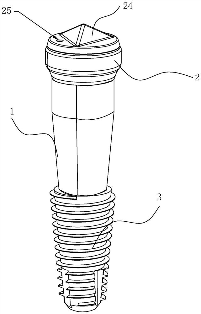
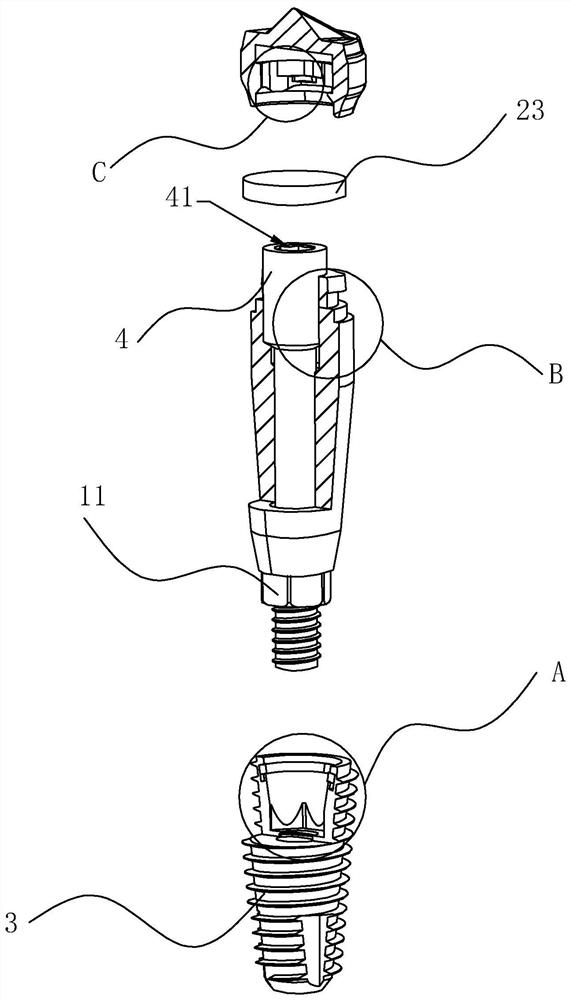
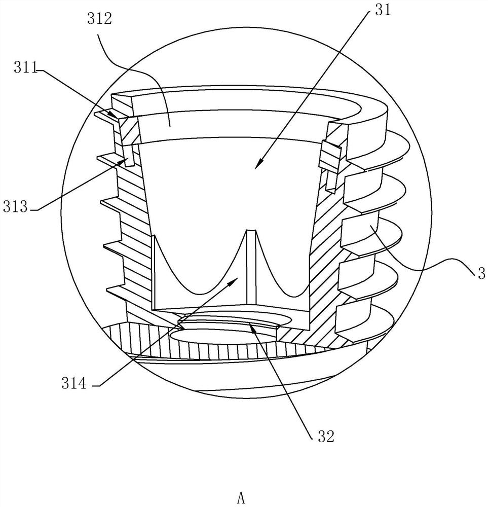
This application relates to a multifunctional scanning healing abutment, including a scanning rod and a cap made of medical rubber. One end of the scanning rod is formed with a nut, and the implant is processed with a hole whose bottom is an internally threaded hole, and the nut is inserted into the internally threaded hole. Cooperate; the inside of the scanning rod is plugged with a central screw that is threadedly connected with the internal threaded hole; the cap is fastened to the end of the scanning rod, and the end of the scanning rod away from the nut is formed with a stepped shaft, and the upper protrusion of the stepped shaft is provided with several sets of limits The inner peripheral surface of the cap is concavely provided with a chute; the upper end of the inner peripheral surface of the hole is concavely provided with a ring groove, and a sealing ring made of cotton spinning is set inside the ring groove, and the scanning rod is sealed and connected with the inner peripheral surface of the sealing ring. . The application improves the airtightness of the scanning healing abutment and the implant during the healing period, reduces the breeding of bacteria in the oral cavity inside the internal threaded hole on the implant, and reduces the cleaning and sterilization operations during the denture implant process.

Description

technical field [0001] The application relates to the field of denture implantation, in particular to a multifunctional scanning healing abutment. Background technique [0002] Dental implants, also known as artificial tooth roots, are structurally divided into three parts, including abutments, implants and central screws. During the implantation process of dental implants, dentists first surgically implant them into the missing teeth In the alveolar bone, after the implant and the alveolar bone heal, the conversion abutment is connected to the implant, and the porcelain crown is buckled and fixed on the conversion abutment to complete the implantation process of the denture. Branemark, a German, used pure titanium metal to make the first titanium nail implant in the mouth of a rabbit in 1965. Later, he conducted functional tests on dogs for 10 years, and achieved good results in in vivo experiments. Compared with traditional fixed bridges and removable dentures, dental imp...

Claims


Application Information

Patent Timeline
Patent Type & Authority Patents(China)
IPC IPC(8): A61C8/00A61C9/00
CPCA61C8/005A61C8/008A61C8/0051A61C8/0068A61C9/0046
Inventor 马胜森彭金东马胜松
Owner 广东威力铭科技有限公司
Why Eureka
Try Eureka