
Continuous flow reaction system

A reaction system and reaction chamber technology, applied in chemical/physical/physical-chemical mobile reactors, crystallization separation, chemical/physical/physical-chemical processes, etc., can solve the problem that reaction equipment is difficult to meet diverse practical application needs , to achieve the effect of solving practical application needs

Inactive Publication Date: 2021-05-25
SHENZHEN E ZHENG TECH
View PDF8 Cites 1 Cited by
  • Summary
  • Abstract
  • Description
  • Claims
  • Application Information

AI Technical Summary

Problems solved by technology

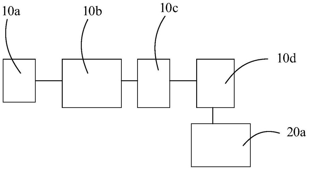
[0003] The main purpose of the present invention is to propose a continuous flow reaction system, which aims to solve the problem that the current reaction equipment is difficult to meet the diverse practical application requirements

Method used


Image

  • Continuous flow reaction system
  • Continuous flow reaction system
  • Continuous flow reaction system

Examples


Embodiment Construction

[0032] The following will clearly and completely describe the technical solutions in the embodiments of the present invention with reference to the accompanying drawings in the embodiments of the present invention. Obviously, the described embodiments are only part of the embodiments of the present invention, not all of them. Based on the embodiments of the present invention, all other embodiments obtained by persons of ordinary skill in the art without creative efforts fall within the protection scope of the present invention.

[0033] It should be noted that if there is a directional indication (such as up, down, left, right, front, back...) in the embodiment of the present invention, the directional indication is only used to explain the position in a certain posture (as shown in the accompanying drawing). If the specific posture changes, the directional indication will also change accordingly.

[0034] In addition, if there are descriptions involving "first", "second" and ...


PUM

PropertyMeasurementUnit
diameteraaaaaaaaaa

Abstract

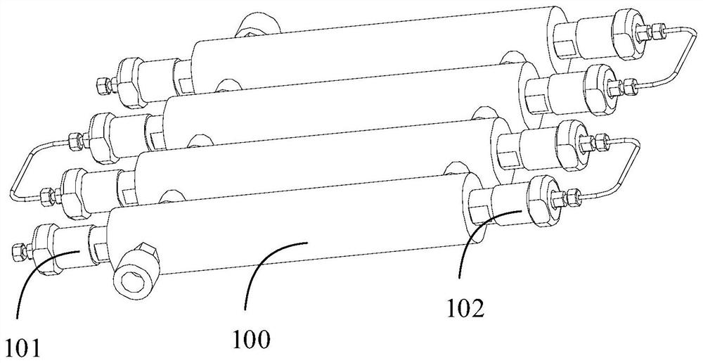
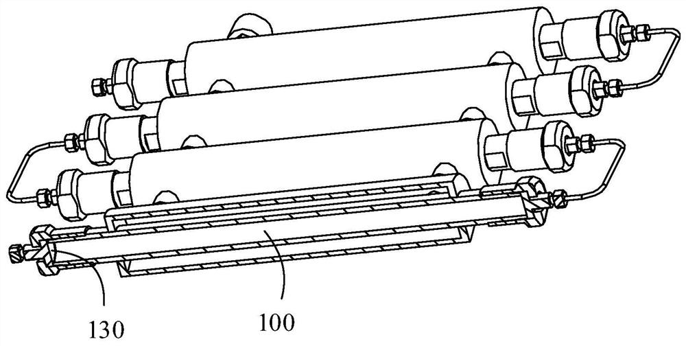
The invention discloses a continuous flow reaction system which comprises first reaction equipment and second reaction equipment, the first reaction equipment is provided with a first reaction cavity, the first reaction cavity is used for reacting one or more of gas-liquid-solid three-phase materials, and the first reaction equipment is provided with an output end; the output end is used for outputting a target product or a mixture of the target product and a catalyst; the second reaction equipment is connected to the output end of the first reaction equipment and is used for accommodating the target product output by the output end of the first reaction equipment, the second reaction equipment is provided with a plurality of heat exchange temperature areas, and the heat exchange temperature areas are arranged independently. According to the technical scheme, the problem that existing reaction equipment is difficult to meet diversified practical application requirements can be solved.

Description

technical field [0001] The invention relates to the technical field of reaction equipment, in particular to a continuous flow reaction system. Background technique [0002] Continuous flow reaction equipment is a commonly used manufacturing equipment in the fields of chemical industry, pharmaceuticals, and new materials. With the development of microchemical technology, continuous flow reaction equipment is developing towards miniaturization and intelligence. Microchannel reactor is an outstanding representative of microchemical technology. Microchannel reactor has excellent mass and heat transfer performance, and has been applied to industrial production fields such as fine chemicals, pharmaceuticals, and new materials. In practical applications, different reactions require different reaction conditions, that is, the requirements in the production process are diverse, and the current reaction equipment is difficult to meet the diverse practical application requirements. C...

Claims


Application Information

Patent Timeline
Patent Type & Authority Applications(China)
IPC IPC(8): B01J19/28B01J8/16B01J8/00B01D9/02
CPCB01J19/285B01J8/16B01J8/008B01D9/0013B01D9/0059B01J2219/00094B01J2208/00212B01D2009/0086
Inventor 张海彬王春李嫣然王志磊游恒志钟明李正强
Owner SHENZHEN E ZHENG TECH
Learn More