Spiral conveyor with auxiliary blades and spiral discharging sedimentation centrifuge

A technology of screw conveyor and auxiliary blade, applied in the field of solid-liquid separation, can solve the problems of low solid content in light phase and poor separation effect, and achieve the effect of low cost, increased area, and improved separation factor Fr

Pending Publication Date: 2021-05-25
JUNENG MACHINERY CHINA
View PDF0 Cites 1 Cited by
  • Summary
  • Abstract
  • Description
  • Claims
  • Application Information

AI Technical Summary

Problems solved by technology

[0004] The applicant aims at the disadvantages of poor separation effect, high solid content in the light phase, and the need for post-treatment procedures to filter or separate solids when the existing equipment groups in the above-mentioned existing production process suspensions that are difficult to separate from solid and liquid. , to provide a screw conveyor with auxiliary blades and a screw discharge sedimentation centrifuge with a reasonable structure. By increasing the equivalent settling area, separation length and increasing speed, the equipment can enhance the processing capacity of the equipment for suspensions that are difficult to separate solids and liquids and separation efficiency, the final light phase has low solid content, and can save space required for equipment, reduce investment and operating costs

Method used


Image

  • Spiral conveyor with auxiliary blades and spiral discharging sedimentation centrifuge
  • Spiral conveyor with auxiliary blades and spiral discharging sedimentation centrifuge
  • Spiral conveyor with auxiliary blades and spiral discharging sedimentation centrifuge

Examples


Embodiment 1

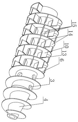
[0030] Such as image 3 , Figure 4 As shown, the screw conveyor with secondary blades of the present invention is between the screw blades 6 of the existing conventional screw conveyor, and several secondary blades 10 are added, and the width of the secondary blades 10 is less than the joint of the screw blades 6. The two adjacent auxiliary blades 10 are arranged alternately, which further divides the original continuous and complete spiral channel space between the spiral blades 6 into meandering flow channels 15, thereby prolonging the separation path length of the suspension and effectively improving the separation effect.

[0031] The auxiliary blade 10 added in this embodiment is a plane straight blade, arranged along the radial direction of the screw conveyor, the bottom side of the root is welded to the outer periphery of the inner cylinder 4, and one side is welded to the helical blade 6, that is The left edge of a part of the auxiliary blades 10 in each helical spac...

Embodiment 2

[0036] Such as Figure 5 As shown, in this embodiment, the plane straight blades in Embodiment 1 are changed to curved blades, and the auxiliary blade 10 has a certain curvature radian, and the curved convex direction of the curved surface is consistent with the direction of rotation of the drum, that is, the heavy phase particles in the suspension It will move outward along the convex surface of the curved blade. This setting can effectively increase the centrifugal force and make the heavy phase particles easy to settle.

Embodiment 3

[0038] Such as Figure 6 , Figure 7 As shown, in this embodiment, the auxiliary blades 10 arranged along the axial direction of the drum in the first embodiment are deflected at a certain angle, Figure 7 The angle α between the middle and auxiliary blades 10 and the central axis of the drum is within 45 degrees, preferably 5-30 degrees, adjacent blades are arranged in parallel, and the deflection directions are consistent. In this embodiment, the auxiliary blade 10 is arranged in the rear spiral channel of the discharge hole 3, which can reduce the conveying resistance in the drying area of ​​the drum cone section 11, and facilitate the discharge of solid-phase materials.


PUM


Abstract

The invention discloses a spiral conveyor with auxiliary blades. A hollow inner barrel is provided with a conical section and a straight barrel section, a feeding hole is formed in the pipe wall close to the conical section, spiral blades are arranged at the periphery of the inner barrel, the plurality of auxiliary blades are arranged between the spiral blades, the width of the auxiliary blades is smaller than the pitch of the spiral blades, and every two adjacent auxiliary blades are arranged in a spiral channel space in a staggered manner to form a zigzag flow channel. The auxiliary blades are additionally arranged between the spiral blades and rotate along with the inner barrel, solid particles of suspension liquid entering the spiral conveyor are separated from a liquid phase under the action of a huge centrifugal force field, and the manner that the liquid is driven to rotate only through the spiral blades originally is changed through the auxiliary blades. The auxiliary blades drive the suspension liquid entering the space between the inner barrel and an outer barrel from discharging holes, so that the centrifugal force and the rotating speed can be immediately obtained, the solid-liquid two-phase separation is accelerated, and the separation efficiency is improved. Meanwhile, the auxiliary blades also increase the equivalent sedimentation area, so that a better separation effect is achieved.

Description

technical field [0001] The invention relates to the technical field of solid-liquid separation, in particular to a screw conveyor with auxiliary blades and a screw discharge sedimentation centrifuge. Background technique [0002] The screw discharge decanter centrifuge includes vertical and horizontal screw discharge decanter centrifuges. It is a high-efficiency centrifugal equipment for solid-liquid separation, and can be used in industrial and civil solid-liquid separation centrifugation processes. Horizontal screw discharge sedimentation centrifuge is referred to as decanter centrifuge for short. Compared with belt filter press and plate and frame filter press, decanter centrifuge has the characteristics of large processing capacity, automatic operation and good dehydration effect. , has been widely used in the industrial field. figure 1 It is an existing conventional decanter centrifuge structure, the drum includes the small end of the cone section 11 and the large end ...

Claims


Application Information

Patent Timeline
IPC IPC(8): B04B1/20
CPCB04B1/20B04B2001/2041B04B2001/205
Inventor 牟富君张后生王斌
Owner JUNENG MACHINERY CHINA
Why Eureka
Try Eureka