Rotating transfer machine

A technology for transferring and loading machines, which is applied in the direction of conveyor objects, metal processing equipment, feeding devices, etc., which can solve problems such as easy water accumulation, loud noise, and collapse, and achieve a high degree of automation, reduce labor intensity, and improve The effect of production efficiency

Pending Publication Date: 2021-05-25
鞍山冶金集团冷轧新材料有限公司
View PDF2 Cites 3 Cited by
  • Summary
  • Abstract
  • Description
  • Claims
  • Application Information

AI Technical Summary

Problems solved by technology

Existing packaging boxes are generally made of steel plates, and its defects are: 1. Due to the large area of ​​the top plate of the packaging box, after being bundled with the steel plate, the top plate of the packaging box is easy to be scratched, and water is easy to accumulate at the deflected place. Rust is easy to occur in water, and in serious cases, the packaging box will be rusted through, which will affect the packaging effect of the packaging box; 2. The stacked steel plates only have the top plate, and the bottom steel plate is still easy to contact the water on the ground, causing the bottom steel plate to rust; 4. Since there is only one top plate, when multiple bundles of steel plates are stacked together, it is easy to cause uneven force on the steel plates and collapse
[0005] In the production process of steel plate packaging boxes, steel plate raw materials and semi-finished products need to be transferred between various equipments. The existing production lines are mostly manually participated, with low efficiency, dusty, loud noise, and harsh working environment, which needs to be improved urgently.

Method used


Image

  • Rotating transfer machine
  • Rotating transfer machine
  • Rotating transfer machine

Examples


Embodiment Construction

[0028] The following will clearly and completely describe the technical solutions in the embodiments of the present invention in conjunction with the accompanying drawings in the present invention. Obviously, the described embodiments are only some of the embodiments of the present invention, not all of them. Based on the embodiments of the present invention, all other embodiments obtained by persons of ordinary skill in the art without making creative efforts belong to the protection scope of the present invention.

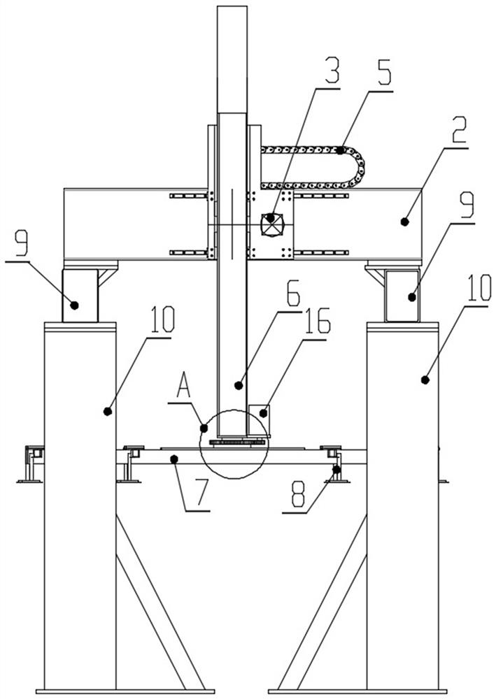
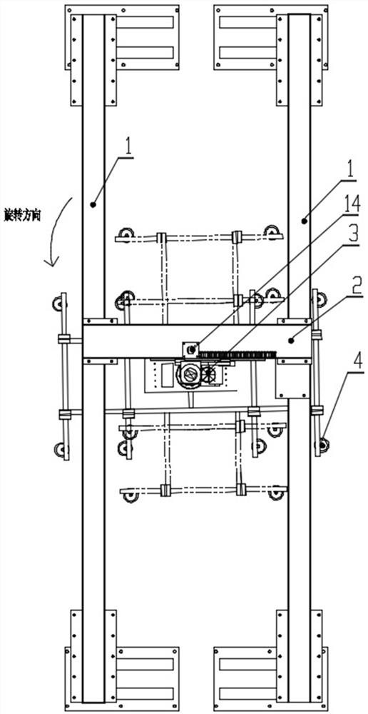
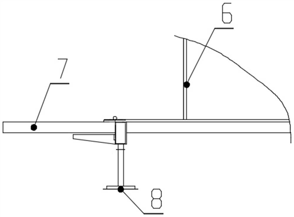
[0029] See Figure 1-Figure 6 , is a structural schematic diagram of an embodiment of the rotary transfer machine of the present invention, including a transverse frame 1, a longitudinal beam 2, a travel mechanism 3 and a pick-up manipulator 4, the two transverse frames 1 are arranged in parallel, the longitudinal beam 2 is centered on the transverse frame 1, and the longitudinal The beam 2 connects two transverse frames 1 to form a space frame structure. The lon...


PUM


Abstract

The invention belongs to the field of industrial continuous production line equipment, and particularly relates to a rotating transfer machine. The rotating transfer machine is characterized by comprising transverse frames, a longitudinal beam, a migration mechanism and a pickup mechanical arm, wherein the longitudinal beam is arranged between the transverse frames, and is arranged on the transverse frames, the two transverse frames are connected through the longitudinal beam to form a space frame structure, the migration mechanism is arranged on the longitudinal beam, a cable drag chain is arranged on the longitudinal beam, and is connected with the migration mechanism, the migration mechanism is connected with the pickup mechanical arm, the pickup mechanical arm comprises a lifting column, a sucker base and suckers, a rotating mechanism is arranged between the bottom end of the lifting column and the sucker base, and the sucker base can rotate relative to the lifting column when driven by the rotating mechanism. Compared with the prior art, the rotating transfer machine has the advantages that the rotating transfer machine can be arranged between two corresponding benders of each steel plate packaging box production line of multiple kinds of steel plate packaging box production lines, and can conduct gripping, lifting, rotating, linear transporting and emptying on semi-finished products, thus the labor intensity is reduced, and the production efficiency is greatly improved.

Description

technical field [0001] The invention belongs to the field of industrial continuous production line equipment, and in particular relates to a rotary transfer machine. Background technique [0002] In order to prevent the steel plate from being damaged by impact or rain erosion during transportation and storage, people have designed a packaging box for steel plate packaging. The packaging box is a rectangular box body consisting of a rectangular top plate and surrounding folds. When packing, the packing box is buckled on the stacked steel plates, and then the steel plates and packing boxes are tied together with steel belts. Existing packaging boxes are generally made of steel plates, and its defects are: 1. Due to the large area of ​​the top plate of the packaging box, after being bundled with the steel plate, the top plate of the packaging box is easy to be scratched, and water is easy to accumulate at the deflected place. Rust is easy to occur in water, and in serious case...

Claims


Application Information

Patent Timeline
Patent Type & Authority Applications(China)
IPC IPC(8): B21D43/18B65G47/91
CPCB21D43/18B65G47/91
Inventor 陈雷毛毳周鑫陈嘉伟
Owner 鞍山冶金集团冷轧新材料有限公司
Why Eureka
Try Eureka