Injection molding system and injection molding method

A technology of injection molding and molding cavity, which is applied in the injection molding system and the field of injection molding, and can solve problems such as difficult cleaning of vent holes, and achieve the effects of simple structure, reduced production cost, and safe and reliable use

Pending Publication Date: 2021-05-25
GREE ELECTRIC APPLIANCES WUHAN +1
View PDF0 Cites 0 Cited by
  • Summary
  • Abstract
  • Description
  • Claims
  • Application Information

AI Technical Summary

Problems solved by technology

[0004] In order to solve all or part of the above-mentioned problems, the purpose of the present invention is to provide an injection molding system and an injection molding method to solve the problem of difficult and slow cleaning of the exhaust hole of the exhaust accessory after it is blocked, which can not only improve the quality of the product , improve production efficiency, and can reduce labor costs and production costs

Method used


Image

  • Injection molding system and injection molding method
  • Injection molding system and injection molding method
  • Injection molding system and injection molding method

Examples


Embodiment Construction

[0023] The present invention will be further described below in conjunction with accompanying drawing.

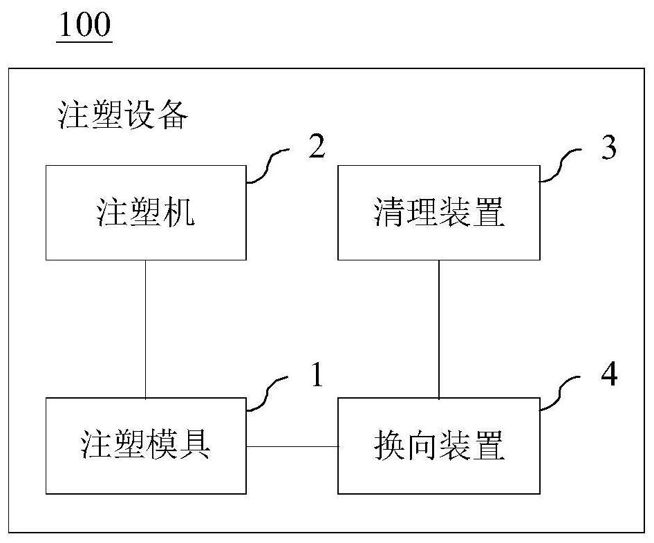
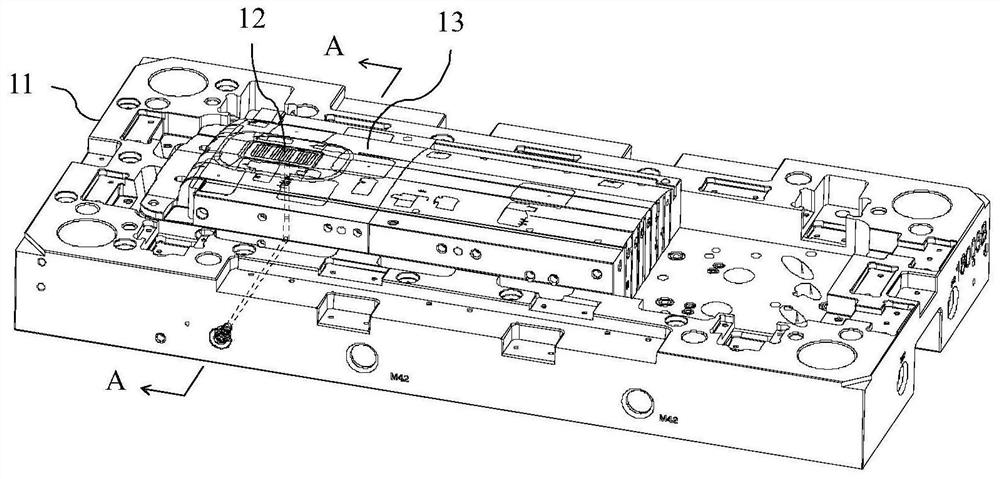
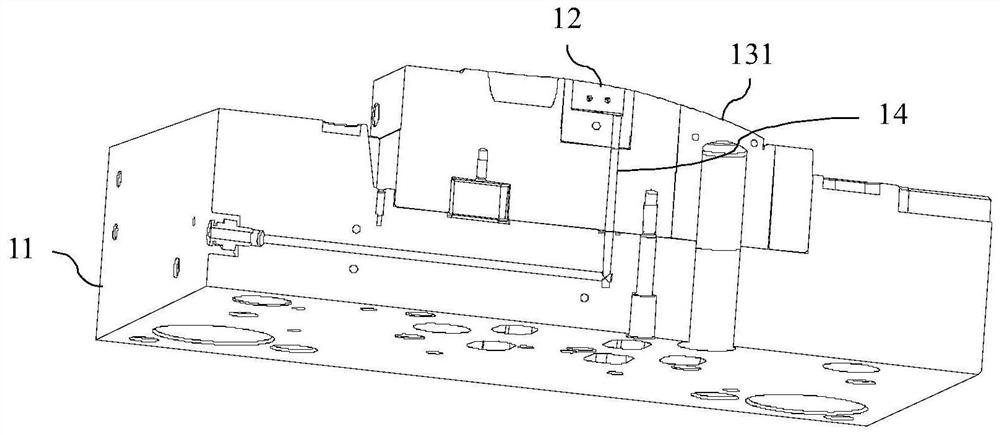
[0024] figure 1 It is a schematic structural diagram of an injection molding system according to an embodiment of the present invention; figure 2 It is a structural diagram of the first mold body of the injection molding system according to the embodiment of the present invention; image 3 for figure 2 The cross-sectional view of the A-A line in the center; Figure 4 It is a top view of the exhaust accessory of the embodiment of the present invention. Such as figure 1 , figure 2 , image 3 and Figure 4 As shown, the embodiment of the present invention provides an injection molding system 100 , and the injection molding system 100 includes an injection mold 1 , an injection molding machine 2 and a cleaning device 3 . Wherein, the injection mold 1 comprises a first mold body 11, a second mold body and an insert part 13 which is arranged on the first mold body 11 a...


PUM


Abstract

The invention relates to an injection molding system and an injection molding method. The injection molding system comprises an injection mold which comprises a first mold body, a second mold body, an insert part with an exhaust accessory, a molding cavity formed among the first mold body, the second mold body and the insert part, a channel arranged in the insert component and the first mold body and connected with an exhaust hole of the exhaust accessory, an injection molding machine and a cleaning device, wherein the injection molding machine can inject molten raw materials into the molding cavity of an injection mold so that the raw materials can be solidified in the molding cavity and molded into a workpiece, and the cleaning device communicates with the channel of the injection mold and can clean the exhaust hole of the exhaust accessory in an air blowing or air exhausting manner after the workpiece is taken out. According to the injection molding system and the injection molding method, the problem that the exhaust hole of the exhaust accessory is difficult and slow to clean after being blocked can be solved, the product quality can be improved, the production efficiency can be improved, and the labor cost and the production cost can be reduced.

Description

technical field [0001] The invention belongs to the technical field of injection molding, and in particular relates to an injection molding system and an injection molding method. Background technique [0002] Nowadays, with the continuous development of the technology level and material technology of injection molded workpieces typical of plastic products, more and more injection molded workpieces are used in industrial products. The main way to produce injection molded workpieces is injection molding, but during the injection molding process, there are often a lot of gas and debris inside the injection mold. If these gases and debris cannot be discharged in time during injection molding, the formed workpiece will appear Air marks, shrinkage, bulging or impurities will have a great impact on thin or transparent injection molding parts, which will not only lead to the direct scrapping of the produced parts, reduce the qualified rate of the product, but also increase the prod...

Claims


Application Information

Patent Timeline
Patent Type & Authority Applications(China)
IPC IPC(8): B29C45/34B29C45/17B29C33/72
CPCB29C33/72B29C45/1753B29C45/34
Inventor 李超夏奎李爽赵伟姜尚文焦海波
Owner GREE ELECTRIC APPLIANCES WUHAN
Why Eureka
Try Eureka