High and low pressure bypass control system for intermediate reheating unit in power generation industry

A bypass system, high-pressure bypass technology, applied in control systems, machines/engines, steam generation, etc., can solve problems such as over-burning thrust tile accidents, high accident rates, and complex layout of high- and low-pressure bypass systems.

Active Publication Date: 2021-05-25
光大环保能源(江阴)有限公司
View PDF4 Cites 3 Cited by
  • Summary
  • Abstract
  • Description
  • Claims
  • Application Information

AI Technical Summary

Problems solved by technology

However, there are many technical problems in the control of the bypass system of the main pipe reheating unit, which hinder the popularization and application of this technology. The details are as follows: the layout of the high and low pressure bypass systems is complicated, and the operation is complicated; the operation of adding and reducing the load of the steam turbine during the boiler combination and steam removal is difficult. , high accident rate
The bypass system of the traditional main pipe reheat unit controls the thrust tile burning accident during the normal load reduction shutdown; after investigation, the two furnaces and one machine mother pipe reheat unit in the operation of the foreign Vietnamese coal power project also occurred during the boiler and steam removal period. The operation of adding and subtracting loads is difficult, and there is an accident of overburning thrust pads

Method used


Image

  • High and low pressure bypass control system for intermediate reheating unit in power generation industry
  • High and low pressure bypass control system for intermediate reheating unit in power generation industry
  • High and low pressure bypass control system for intermediate reheating unit in power generation industry

Examples


Embodiment 1

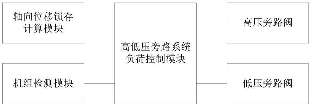
[0029] figure 1 It is a functional block diagram of the high and low pressure bypass control system of the intermediate reheat unit used in the power generation industry of the present invention.

[0030] In this example, if figure 1As shown, this embodiment provides a high and low voltage bypass control system for waste power generation industry, which includes: a high and low voltage bypass system load control module, electrically connected to the high and low voltage bypass system load control module The axial displacement lock calculation module, the unit detection module, the high pressure bypass valve and the low pressure bypass valve; wherein the high and low pressure bypass system load control module is suitable for locking the current axial displacement value according to the operating state of the steam turbine, and controlling the corresponding The bypass valve performs loading or unloading actions; the axial displacement latch calculation module is suitable for ca...

Embodiment 2

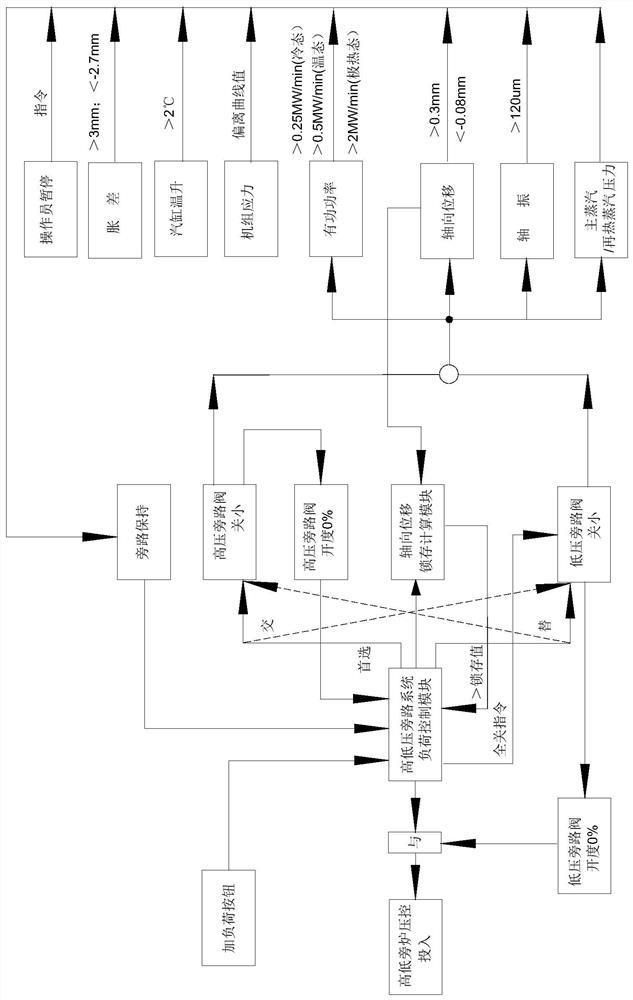
[0044] Figure 5 It is a flow chart of the boiler parallel steam automatic loading method of the present invention.

[0045] On the basis of Example 1, such as Figure 5 As shown, this embodiment provides an automatic loading method for the intermediate reheat unit after the boiler is combined with steam, which includes: after the boiler is started and steamed, lock the current axial displacement value of the steam turbine, and gradually reduce the corresponding high Bypass valve: real-time detection of unit load increase rate, cylinder temperature increase rate, expansion difference change and unit stress, when the cylinder temperature increase rate and expansion difference change reach the set value, the high-pressure bypass valve stops closing and keeps at Warm up the engine at this opening; calculate the difference between the axial displacement increase and the locked axial displacement value, stop closing the high-pressure bypass valve when the difference reaches the se...

Embodiment 3

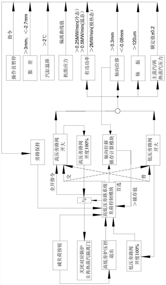
[0049] Figure 6 It is a flow chart of the automatic load reduction method for boiler disassembly of the present invention.

[0050] On the basis of the above examples, if Figure 6 As shown, this embodiment provides an automatic load reduction method for boiler delisting, which includes: after setting the boiler to be decommissioned and out of service, lock the current axial displacement value of the steam turbine, and gradually increase the corresponding low pressure bypass at a set rate. By-pass valve; real-time detection of unit load drop rate, cylinder temperature drop rate, expansion difference change and unit stress, when any parameter reaches the corresponding set value, the low-pressure bypass valve stops opening and keeps it at the opening for warm-up ; Calculate the difference between the axial displacement reduction and the locked axial displacement value, stop opening the low-pressure bypass valve when the difference reaches the set value, and start to open the c...


PUM


Abstract

The invention particularly relates to a high and low pressure bypass control system for an intermediate reheating unit in the power generation industry. The high and low pressure bypass control system comprises a high and low pressure bypass system load control module, an axial displacement latch calculation module, a unit detection module, a high pressure bypass valve and a low pressure bypass valve; the current axial displacement value is locked according to the running state of a steam turbine, and a corresponding bypass valve is controlled to execute the load increasing or load decreasing action; and the axial displacement latch calculation module is suitable for calculating the axial displacement variable quantity, and the unit detection module is suitable for detecting the unit load rise rate, the cylinder temperature rise rate, the differential expansion variable quantity and the unit stress, that is, the high-pressure bypass valve and the low-pressure bypass valve are alternately controlled to execute corresponding actions. The high and low pressure bypass control system has the function of automatically controlling the high-pressure bypass and the low-pressure bypass during the load increasing and reducing period of the steam turbine during the steam merging and steam releasing period of a boiler, and solves the problem that the traditional high-pressure bypass system and the traditional low-pressure bypass system have the thrust pad burning accident during the normal load reducing shutdown period.

Description

technical field [0001] The invention belongs to the technical field of reheating units, in particular to a high and low pressure bypass control system for intermediate reheating units used in the power generation industry. Background technique [0002] As my country's urbanization rate and people's attention to the living environment continue to increase, the market competition in the waste incineration power generation industry is fierce, and the waste disposal fee is getting lower and lower. The space is getting narrower and narrower. At present, the thermal efficiency of the whole plant of domestic conventional waste-to-energy projects is about 21%. The third phase of Jiangyin project adopts the reheating technology of two furnaces and one machine mother control in the industry. According to the third-party function test, the thermal efficiency of the whole plant reaches 28.69%, and the power generation capacity of 1 ton of waste into the furnace is 595kW.h / t. However, t...

Claims


Application Information

Patent Timeline
Patent Type & Authority Applications(China)
IPC IPC(8): F22B35/00F01K11/02F01K13/02F01K7/02F01K7/16
CPCF22B35/00F01K11/02F01K13/02F01K7/02F01K7/16Y02E20/12
Inventor 王文秀王雪炎桂宏桥刘喜李德丰储开建邵明军
Owner 光大环保能源(江阴)有限公司
Why Eureka
Try Eureka