
Optical transmitting assembly, optical transmitting and receiving module and optical fiber cable module

A technology of light emitting components and light emitters, applied in optics, optical components, electromagnetic transceivers, etc., can solve problems such as restrictions on electrical connectors, achieve the effects of avoiding reflections, simplifying the manufacturing process, and reducing manufacturing costs

Inactive Publication Date: 2021-05-25
YU SHENG PHOTOELECTRIC CO LTD
View PDF4 Cites 0 Cited by
  • Summary
  • Abstract
  • Description
  • Claims
  • Application Information

AI Technical Summary

Problems solved by technology

Therefore, the electrical I / O signal rate will be limited by the electrical characteristics of the electrical connector

Method used


Image

  • Optical transmitting assembly, optical transmitting and receiving module and optical fiber cable module
  • Optical transmitting assembly, optical transmitting and receiving module and optical fiber cable module
  • Optical transmitting assembly, optical transmitting and receiving module and optical fiber cable module

Examples


Embodiment Construction

[0037] The following descriptions of the various embodiments refer to the accompanying drawings to illustrate specific embodiments in which the present invention can be practiced. The directional terms mentioned in the present invention, such as "up", "down", "front", "back", "left", "right", "inside", "outside", "side", etc., are for reference only The orientation of the attached schema. Therefore, the directional terms used are used to illustrate and understand the present invention, but not to limit the present invention.

[0038] The drawings and descriptions are to be regarded as illustrative in nature and not restrictive. In the figures, structurally similar units are denoted by the same reference numerals. In addition, the size and thickness of each component shown in the drawings are arbitrarily shown for understanding and ease of description, but the present invention is not limited thereto.

[0039] In the drawings, the thickness of layers, films, panels, regions,...


PUM


Abstract

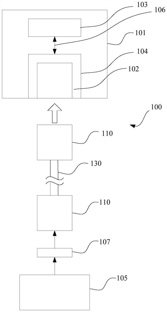
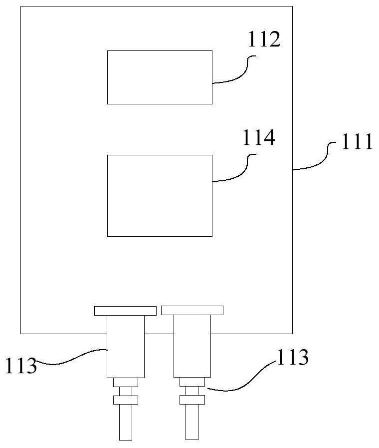
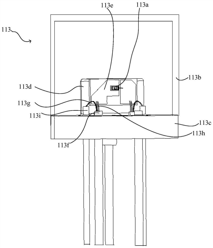
The invention provides a light emitting assembly, an optical transmitting and receiving module and an optical fiber cable module. The optical transmitting and receiving module comprises a substrate, a light receiving assembly and a light emitting assembly, the light emitting assembly comprises a light emitter, a sealed shell, a circuit substrate and a capacitor; the light emitter, the circuit substrate and the capacitor are arranged in the sealed shell, the light emitter is arranged on the circuit substrate, the capacitor is electrically connected between the inner pin of the light emitting assembly and the circuit substrate. According to the invention, the system impedance of the light emitting assembly can be adjusted.

Description

technical field [0001] The invention relates to the technical field of optical fiber communication, in particular to an optical transceiver module and an applied optical fiber cable module. Background technique [0002] In the application of optical fiber communication technology, it is necessary to convert an electrical signal into an optical signal through an optical emitting component (such as a laser), and then couple the optical signal into an optical fiber that conducts the optical signal. [0003] At present, the demand for computing devices continues to rise, and even the demand for computing devices to achieve higher performance is also increasing. However, traditional electrical I / O (input / output) signal transmission is not expected to keep pace with the demand for increased performance, especially for future high-performance computing expectations. Today, I / O signals are routed electrically to and from the processor through the circuit board and out to peripheral...

Claims


Application Information

Patent Timeline
IPC IPC(8): G02B6/42H04B10/40
CPCG02B6/4251G02B6/4274G02B6/428G02B6/4245H04B10/40
Inventor 吕政鸿陈珉儒蔡智韦李文贤张骏扬
Owner YU SHENG PHOTOELECTRIC CO LTD
Learn More