Optical imaging system, image capturing device and electronic equipment

An optical imaging system, image-side technology, applied in optics, optical components, instruments, etc., can solve problems such as inability to monitor drivers and low resolution

Pending Publication Date: 2021-05-25
JIANGXI JINGCHAO OPTICAL CO LTD
View PDF0 Cites 2 Cited by
  • Summary
  • Abstract
  • Description
  • Claims
  • Application Information

AI Technical Summary

Problems solved by technology

However, the existing camera devices that meet the requirements of vehicle miniaturization have low resolution and cannot monitor the state of the...

Method used


Image

  • Optical imaging system, image capturing device and electronic equipment
  • Optical imaging system, image capturing device and electronic equipment
  • Optical imaging system, image capturing device and electronic equipment

Examples


no. 1 example

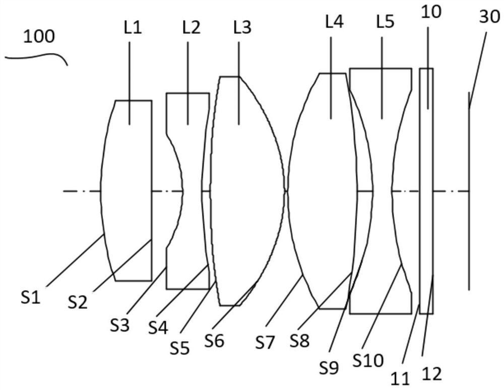
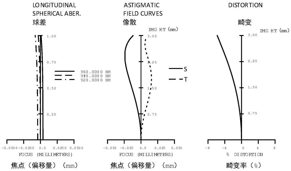
[0177] See Picture 1-1 and Figure 1-2 ,in Picture 1-1 It is a schematic structural diagram of the optical imaging system 100 of the first embodiment, Figure 1-2 From left to right are the spherical aberration, astigmatism and distortion curves of the first embodiment of the present invention. Depend on Picture 1-1 It can be seen that the optical imaging system 100 of this embodiment includes a first lens L1 with positive refractive power, a second lens L2 with negative refractive power, a third lens L3 with positive refractive power, and a third lens L3 with positive refractive power from the object side to the image side. The fourth lens L4 with positive refractive power, the fifth lens L5 with negative refractive power, the protective glass 10 and the imaging surface 30 . The optical imaging system 100 further includes an infrared bandpass filter film (not shown in the figure), which is coated on the image side S2 of the first lens L1 .

[0178] The first lens L1 is m...

no. 2 example

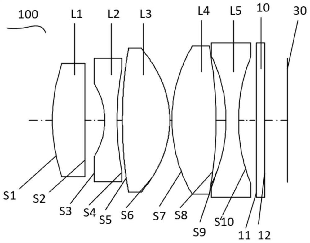
[0192] See diagram 2-1 and Figure 2-2 ,in diagram 2-1 It is a schematic structural diagram of the optical imaging system 100 of the second embodiment, Figure 2-2 From left to right are the spherical aberration, astigmatism and distortion curves of the second embodiment of the present invention. Depend on diagram 2-1 It can be seen that the optical imaging system 100 of this embodiment includes a first lens L1 with positive refractive power, a second lens L2 with negative refractive power, a third lens L3 with positive refractive power, and a third lens L3 with positive refractive power from the object side to the image side. The fourth lens L4 with positive refractive power, the fifth lens L5 with negative refractive power, the protective glass 10 and the imaging surface 30 . The optical imaging system 100 further includes an infrared bandpass filter film (not shown in the figure), which is coated on the image side S2 of the first lens L1 .

[0193] The first lens L1...

no. 3 example

[0206] See Figure 3-1 and Figure 3-2 ,in Figure 3-1 It is a schematic structural diagram of the optical imaging system 100 of the third embodiment, Figure 3-2 From left to right are the spherical aberration, astigmatism and distortion curves of the third embodiment of the present invention. Depend on Figure 3-1 It can be seen that the optical imaging system 100 of this embodiment includes a first lens L1 with positive refractive power, a second lens L2 with negative refractive power, a third lens L3 with positive refractive power, and a third lens L3 with positive refractive power from the object side to the image side. The fourth lens L4 with positive refractive power, the fifth lens L5 with negative refractive power, the protective glass 10 and the imaging surface 30 . The optical imaging system 100 further includes an infrared bandpass filter film (not shown in the figure), which is coated on the image side S2 of the first lens L1 .

[0207] The first lens L1 is m...


PUM


Abstract

The invention provides an optical imaging system, and the system sequentially comprises, from an object side to an image side, a first lens with positive focal power, wherein the object side surface of the first lens is a convex surface; asecond lens with negative focal power, wherein the object side surface and the image side surface of the second lens are concave surfaces; a third lens with positive focal power, wherein the object side surface and the image side surface of the third lens are convex surfaces; a fourth lens with positive focal power, wherein the object side surface and the image side surface of the fourth lens are convex surfaces; and a fifth lens with negative focal power, wherein the object side surface and the image side surface of the fifth lens are concave surfaces. The optical imaging system has the advantages of high pixel resolution and small size. In addition, the invention also provides an image capturing device and electronic equipment.

Description

technical field [0001] The invention relates to optical imaging technology, in particular to an optical imaging system, an imaging device and electronic equipment. Background technique [0002] With the popularity of automobiles, traffic accidents caused by factors such as fatigue driving occur frequently. With the rapid development of the vehicle industry, vehicle driving technologies such as ADAS (Advanced Driving Assistant System) and DMS (Driver Monitor System) are gradually becoming mature, and the development of these vehicle technologies is inseparable from camera technology. However, the existing camera devices that meet the requirements of vehicle miniaturization have low resolution and cannot monitor the state of the driver well. The information can be used to speculate and judge whether the driver is driving in fatigue, so as to provide early warning and improve driving safety. Contents of the invention [0003] In view of this, the present invention provides ...

Claims


Application Information

Patent Timeline
IPC IPC(8): G02B13/00G02B13/18
CPCG02B13/0045
Inventor 蔡雄宇兰宾利周芮
Owner JIANGXI JINGCHAO OPTICAL CO LTD
Why Eureka
Try Eureka