Design method of X-waveband high-Q-value SIW transmission line

A design method and transmission line technology, applied in the microwave field, can solve problems such as high Q value optimization, and achieve optimal design, low loss, and high Q value

Inactive Publication Date: 2021-05-25
UNIV OF ELECTRONIC SCI & TECH OF CHINA
View PDF5 Cites 0 Cited by
  • Summary
  • Abstract
  • Description
  • Claims
  • Application Information

AI Technical Summary

Problems solved by technology

[0005] In view of the above-mentioned problems or deficiencies, in order to solve the problem that the existing X-band substrate integrated waveguide SIW design cannot achieve higher Q value optimization: the present invention provides a design method for an X-band high-

Method used


Image

  • Design method of X-waveband high-Q-value SIW transmission line
  • Design method of X-waveband high-Q-value SIW transmission line
  • Design method of X-waveband high-Q-value SIW transmission line

Examples


Embodiment Construction

[0030]The present invention will be further described below with reference to the accompanying drawings and examples.

[0031]Design method of X-band high Q value SIW transmission line, including the following steps:

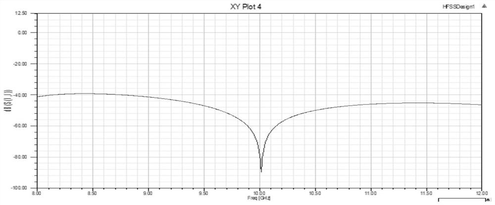
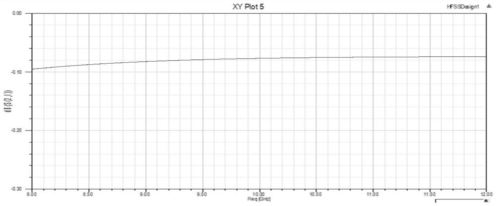
[0032]Step 1, first, a SIW transmission line having a central frequency is 10 GHz. Reach the following indicator requirements: 1) Frequency range: 8 ~ 12GHz; 2) Insertion loss: within 0.5 dB; 3) Echo loss: -30dB or less.

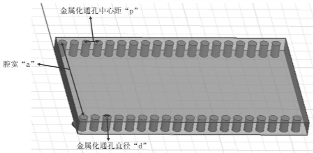
[0033]The three-dimensional structure of the transmission line isfigure 1 As shown, the return loss isfigure 2 As shown, insertion loss isimage 3 Indicated. The transmission line selects a material having a relative dielectric constant of 2.4 as a dielectric substrate, and then parallel the two rows of metallized through holes on the dielectric substrate. Finally, two metal plates are covered with substantially lower surfaces of the medium. The left and right ends of the medium substrate are "1 wave port" and "2 wave port", respectively.

[0034]Step 2, the fir...


PUM


Abstract

The invention relates to a microwave technology, in particular to a design method of an X-waveband high-Q-value SIW transmission line. From the perspective of the Q value, the relationship between the Q value of the X-band SIW and each parameter (d, p, a) is researched. The method comprises the following steps: firstly, carrying out gradual simulation analysis on a transmission line model by utilizing three-dimensional electromagnetic simulation software HFSS so as to obtain relatively reliable experimental data, and carrying out formula fitting by utilizing MATLAB so as to obtain a relation curve of a Q value, d and p and a corresponding fitting formula; then, obtaining the optimal combination between the high Q value of the substrate integrated waveguide (SIW) and various parameters through the obtained fitting formula. The high Q value design of the X-waveband SIW transmission line is realized on the premise that other parameters are met, the range of various parameters given by a traditional design formula is narrowed, and a more accurate quantitative relation is given.

Description

Technical field[0001]The present invention relates to microwave techniques, specifically a design method of X-band high Q value SiW transmission line.Background technique[0002]The X band is a radio wave section of 8-12 GHz and belongs to microwaves in electromagnetic spectroscopy. Widely used in satellite communication, broadcast, meteorological satellite, and earth detection. With the continuous development of electronic technology, people's requirements for microwave metaders are also increasing, due to the large waveguide, and the microstrip and other plane transmission lines are easy to integrate, but the loss is too large. Therefore, the Substrate Integrated Waveguide, referred to as SiW will come.[0003]In microwave device design, the performance of the transmission line is particularly important. The substrate integrated waveguide (SiW) is a transmission line structure having a higher Q value, a lower radiation, and a small amount of small weight and easy integration.[0004]Tra...

Claims


Application Information

Patent Timeline
IPC IPC(8): H01P3/12H01P11/00G06F30/20
CPCG06F30/20H01P3/121H01P11/002
Inventor 汪晓光孙佳栋马洪泽王浩川韩天成杨光
Owner UNIV OF ELECTRONIC SCI & TECH OF CHINA
Why Eureka
Try Eureka