Blood sample collection equipment for hemodialysis department
A technology of hemodialysis and collection equipment, applied in the field of hemodialysis, which can solve the problems of patients catching cold and inconvenient blood sample test tube shock absorption, clamping and protection
- Summary
- Abstract
- Description
- Claims
- Application Information
AI Technical Summary
Problems solved by technology
Method used
Image
Examples
Embodiment 1
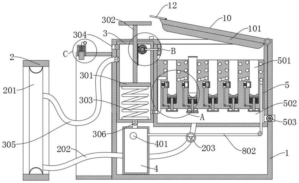
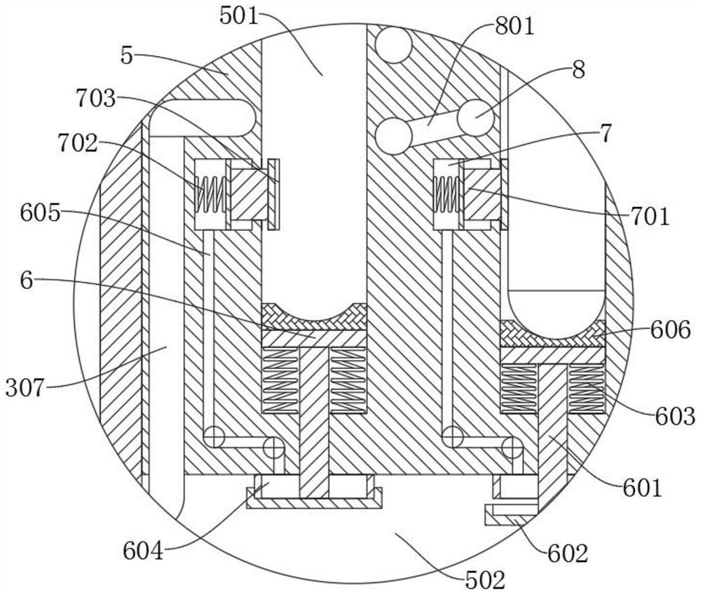
[0036] refer to Figure 1-4 , a blood sample collection device for hemodialysis department, comprising a box body 1, the side wall of the box body 1 is provided with a flow stop sleeve 2, the flow stop sleeve 2 is provided with an elastic air bag 201, and the box body 1 is provided with an exhaust mechanism, A first exhaust pipe 305 is connected between the output end of the pumping and exhausting mechanism and the elastic air bag 201, and a box door 10 is rotatably connected to the box body 1, and a placement frame 5 is fixedly connected to the box body 1. A plurality of sets of fixed tubes 501, a cavity 502 is provided at the bottom of the shelf 5, a first air guide tube 202 is connected between the elastic airbag 201 and the cavity 502, and a control valve 203 is provided on the first air guide tube 202, and the fixed tube 501 slides Bottom bracket 6 is connected, and the bottom of bottom bracket 6 is fixedly connected with connecting rod 601. The end of connecting rod 601 ...
Embodiment 2
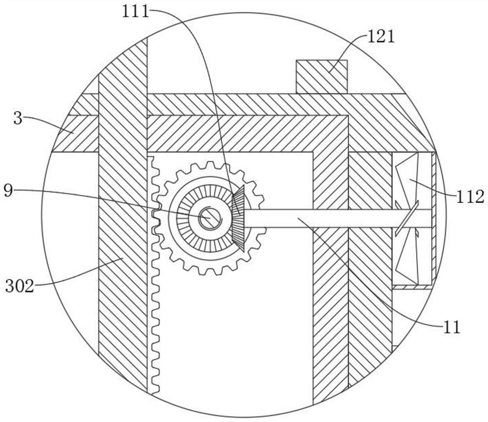
[0039] refer to Figure 1-4 , a blood sample collection device for hemodialysis department, which is basically the same as that in Embodiment 1, furthermore, the exhaust mechanism includes a cylinder 3, a piston 301 is slidably connected to the cylinder 3, and a first spring 303 is fixedly connected to the bottom of the piston 301 , the end of the first spring 303 away from the piston 301 is fixedly connected to the inner wall of the cylinder 3, the end of the piston 301 away from the first spring 303 is fixedly connected with a push rod 302, the cylinder 3 is provided with a first air intake pipe 304, the cylinder 3 and the elastic airbag 201 is fixedly connected with the first exhaust pipe 305, the first air intake pipe 304 and the first exhaust pipe 305 are provided with check valves, and the staff presses the push rod 302 repeatedly to cooperate with the first spring 303 to make the piston 301 in the The cylinder 3 reciprocates and slides to guide the outside air into the ...
Embodiment 3
[0041] refer to Figure 1-4 , a blood sample collection device for hemodialysis department, which is basically the same as that of Embodiment 1. Furthermore, a cooling tube 8 is provided in the placement frame 5, and the cooling tube 8 matches the position of the fixed tube 501, and the position between the adjacent cooling tubes 8 A conduit 801 is connected between them, a cold air box 4 is arranged in the box body 1, a second intake pipe 306 is connected between the cylinder 3 and the cold air box 4, a second exhaust pipe 307 is connected between the cylinder 3 and the cooling pipe 8, and the second exhaust pipe 307 is connected between the cylinder 3 and the cooling pipe 8. The two intake pipes 306 and the second exhaust pipe 307 are all provided with check valves, the first air intake pipe 304 and the first exhaust pipe 305 are located on the same side of the piston 301, the second air intake pipe 306 and the second exhaust pipe 307 Located on the side of the piston 301 aw...
PUM
 Abstract
Description
Claims
Application Information
 - R&D
- Intellectual Property
- Life Sciences
- Materials
- Tech Scout
- Unparalleled Data Quality
- Higher Quality Content
- 60% Fewer Hallucinations
Browse by: Latest US Patents, China's latest patents, Technical Efficacy Thesaurus, Application Domain, Technology Topic, Popular Technical Reports.
© 2025 PatSnap. All rights reserved.Legal|Privacy policy|Modern Slavery Act Transparency Statement|Sitemap|About US| Contact US: help@patsnap.com


