Particle capturing device and GIS/GIL cylinder structure

A capture device and particle technology, applied in particle charging/ionization places, solid separation, electrostatic effect separation, etc., can solve the problem of a small amount of particles jumping out of the trap in reverse, to improve particle capture efficiency, improve foreign particles, and improve operation reliability. sexual effect

Pending Publication Date: 2021-05-28
HENAN PINGGAO ELECTRIC +2
View PDF9 Cites 1 Cited by
  • Summary
  • Abstract
  • Description
  • Claims
  • Application Information

AI Technical Summary

Problems solved by technology

[0005] The purpose of the present invention is to provide a particle trapping device to solve the technical problem that the particle trap in the prior art is only provided with a single grid plate to form a single-layer capture trap, which makes it easy for a small amount of particles to jump out of the trap in reverse

Method used


Image

  • Particle capturing device and GIS/GIL cylinder structure
  • Particle capturing device and GIS/GIL cylinder structure
  • Particle capturing device and GIS/GIL cylinder structure

Examples


Embodiment 1

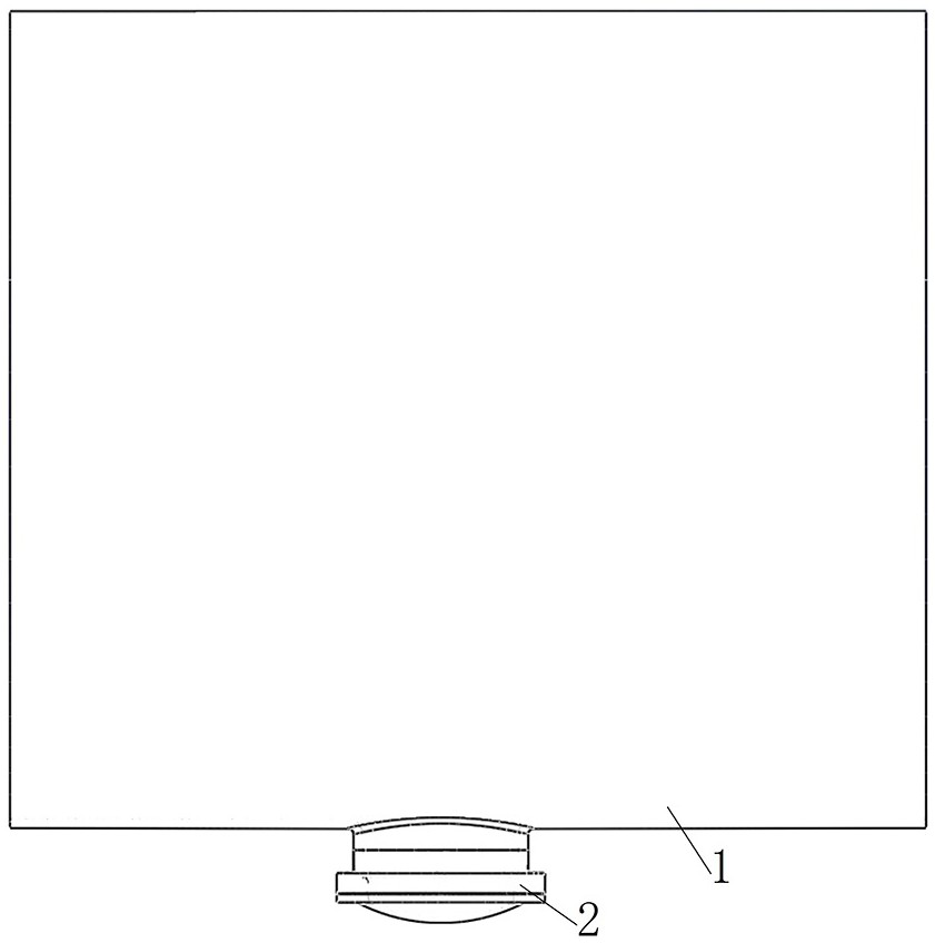
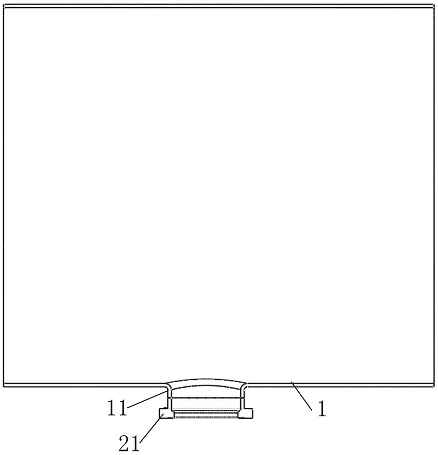
[0066] In the GIS cylinder structure provided by the present invention, in the particle capture device installed on the opening of the cylinder wall of the cylinder 1, two grid plates are arranged, which are all metal parts, so as to facilitate the formation of an equipotential area, and then in the particle capture Device 2 forms upper and lower layers of capture traps. Under the action of gravity, electric field and air flow, particles will pass through the upper layer of capture traps and enter the lower layer of capture traps. Even if a small amount of particles jump out of the lower layer of particle traps, they will fall into the upper layer of particle traps , will not directly return to the cylinder 1, thereby effectively improving the particle capture efficiency of the particle capture device 2.

[0067] The structure of the GIS cylinder in this embodiment is as follows Figure 1 to Figure 4 As shown, it includes a cylinder 1, an opening is provided on the cylinder wa...

Embodiment 2

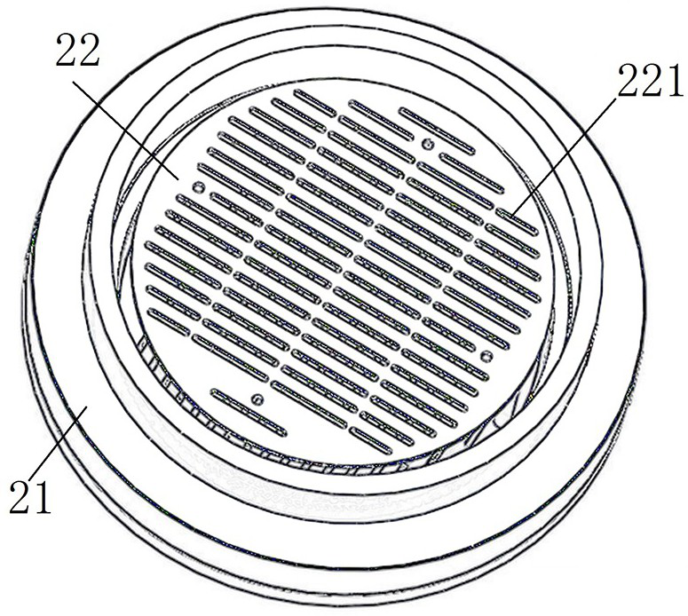
[0083] It differs from Embodiment 1 mainly in that: in Embodiment 1, the upper grid holes and the lower grid holes are arranged vertically and alternately. In this embodiment, both the upper grid holes and the lower grid holes are still long hole structures and arranged in a staggered manner, and the angle between them is less than 90°.

Embodiment 3

[0085] The main difference from Embodiment 1 is that in Embodiment 1, glue is applied on the upper surfaces of the two grid plates to form an adhesive layer. In this embodiment, glue can also be applied only on the upper surface of the upper grid plate or the lower grid plate to form an adhesive layer for gluing and capturing particles.


PUM


Abstract

The invention relates to a particle capturing device and a GIS / GIL cylinder structure. The particle capturing device comprises a trap cover plate, a lower grid plate, and anupper grid plate, wherein the lower grid plate is fixedly mounted on the trap cover plate, so that the lower grid plate and the trap cover plate are matched to form a lower-layer capturing trap; the upper grid plate and the lower grid plate are relatively and fixedly assembled, the upper grid plate is parallel to the lower grid plate, and the upper grid plate is located above the lower grid plate, so that the upper grid plate and the lower grid plate form an upper-layer capturing trap. The two grid plates and the trap cover plate are utilized to form an upper-layer capturing trap and a lower-layer capturing trap, particles can penetrate through the upper-layer capturing trap to enter the lower-layer capturing trap under the action of gravity, an electric field and airflow, and even if a small amount of particles jump out of the lower-layer particle trap, the particles can fall into the upper-layer particle trap and cannot directly return to the cylinder body, therefore, the particle capturing efficiency of the particle capturing device is effectively improved.

Description

technical field [0001] The invention relates to a particulate capture device and a GIS / GIL cylinder structure. Background technique [0002] GIS is an important equipment in the field of power transmission, and its safety and reliability have a vital impact on the power grid. According to the relevant information of the power grid company, there have been too many failures of the fracture shield to discharge the cylinder in GIS, resulting in huge economic losses. The direct cause of GIS gap discharge is the presence of foreign matter inside it, which reduces the insulation performance of the product. Studies have shown that foreign objects in the GIS fracture shield will fall on the inner wall of the cylinder under the influence of airflow disturbance and operating vibration. , causing the electric field at this location to be distorted, eventually causing a discharge failure. [0003] In order to improve the reliability of GIS products and reduce the failure rate of prod...

Claims


Application Information

Patent Timeline
Patent Type & Authority Applications(China)
IPC IPC(8): B03C3/38B03C3/34B03C3/017
CPCB03C3/38B03C3/34B03C3/017
Inventor 付佳佳卢鹏王丽娟程伟然方启王磊王志彪刘斯腾随祥旭常克歌王保刚杨向龙张建周张锐刘佳春亢苏占吴麒
Owner HENAN PINGGAO ELECTRIC
Why Eureka
Try Eureka