Polishing equipment for multi-axis free-form surface optical element and working method

An optical element, free technology, used in grinding/polishing equipment, optical surface grinder, metal processing equipment, etc., can solve the problem of difficult processing and manufacturing of multi-axis free-form optical elements

Pending Publication Date: 2021-05-28
湖南大敏尚东精密机械有限公司
View PDF0 Cites 4 Cited by
  • Summary
  • Abstract
  • Description
  • Claims
  • Application Information

AI Technical Summary

Problems solved by technology

However, the processing and manufacturing of multi

Method used


Image

  • Polishing equipment for multi-axis free-form surface optical element and working method
  • Polishing equipment for multi-axis free-form surface optical element and working method
  • Polishing equipment for multi-axis free-form surface optical element and working method

Examples


Embodiment Construction

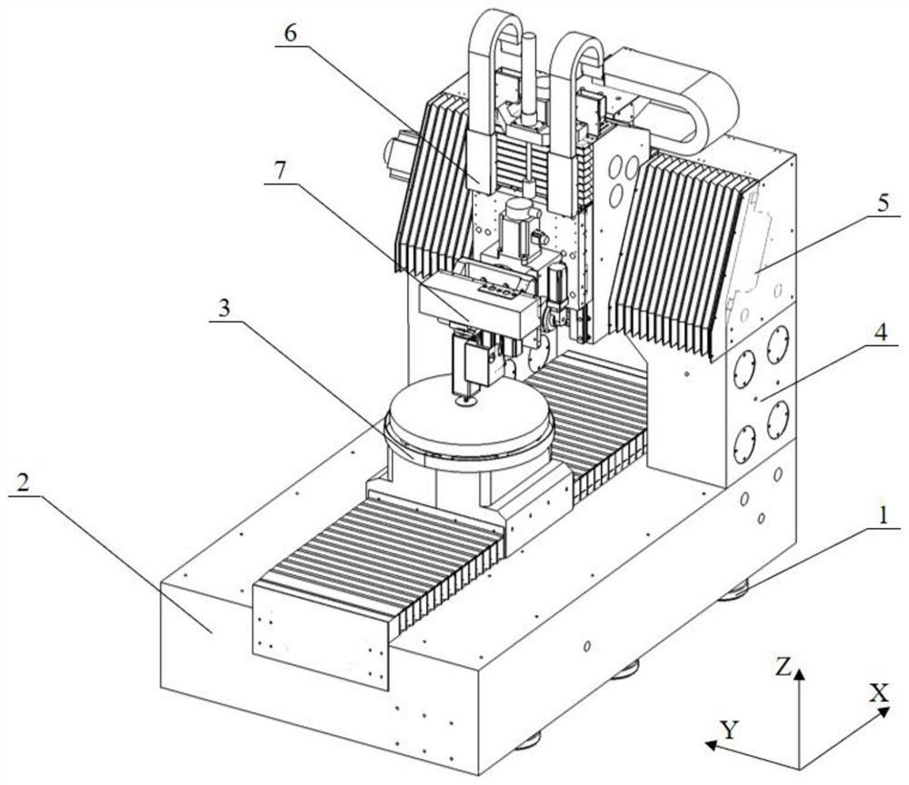
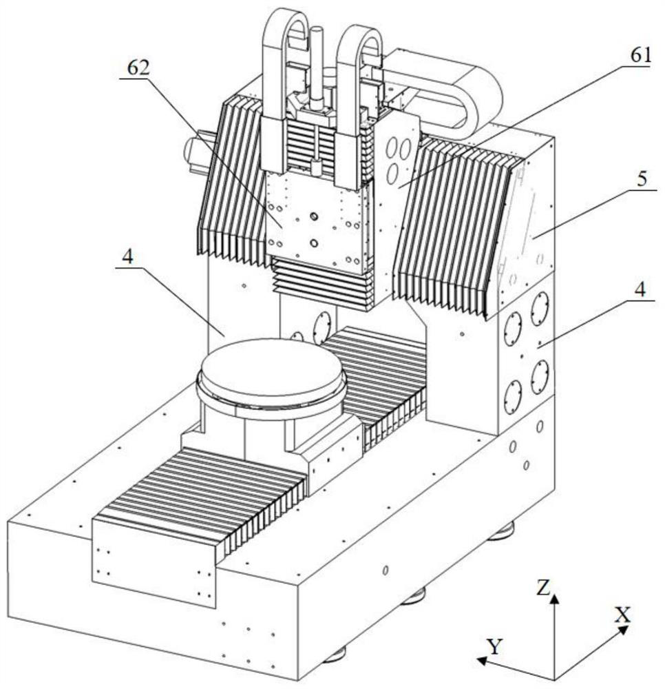
[0027] Such as Figure 1-7 As shown, the polishing equipment for multi-axis free-form surface optical components includes: bed 2, workpiece clamping platform 3, column 4, beam 5, linear motion mechanism 6, multi-axis free-form surface polishing device 7,

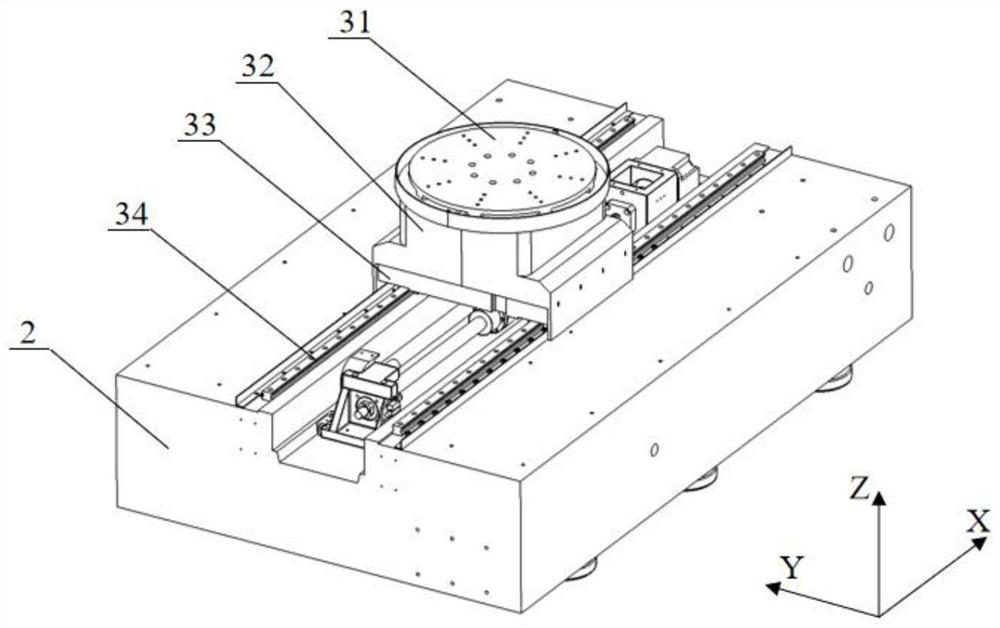
[0028] The bed 2 is placed horizontally, the workpiece clamping platform 3 is installed on the bed and includes: fixture 31, high-precision turntable 32, X-axis linear motion sliding plate 33 and X-axis linear motion guide rail 34, and fixture 31 is fixed on the high-precision turntable 32 , the workpiece to be processed is placed horizontally on the high-precision turntable 32 through the fixture. The high-precision turntable is fixed on the X-axis linear motion slide plate 33, and performs high-precision servo rotation around the C axis perpendicular to the bed. The X-axis linear motion slide plate is installed On the X-axis linear motion guide rail and perform linear motion along the X-axis direction;

[0029] The column...


PUM


Abstract

The invention discloses polishing equipment for a multi-axis free-form surface optical element and a working method. A lathe bed is horizontally placed, and a workpiece to be machined is horizontally placed on a high-precision rotary table through a clamp, so that positioning and clamping are facilitated, the machining efficiency is improved, the clamping difficulty and deformation caused by clamping are reduced, and the large-diameter free-form surface optical element can be machined. The high-precision rotary table can move along the X axis relative to the lathe bed and rotate around the C axis, a multi-axis free-form surface polishing device can move on a cross beam in the Y-axis direction and the Z-axis direction, and can conduct servo rotation around an A axis parallel to the X axis and a B axis parallel to the Y axis. Therefore, the optical element subjected to ultra-precision turning and grinding can be further shaped, and the precision better than that of traditional machining can be achieved.

Description

technical field [0001] The invention relates to the technical field of ultra-precision machining of optical elements, in particular to a polishing device for multi-axis free-form surface optical elements and a working method of the polishing device. Background technique [0002] In the past half a century, mankind has made rapid progress in the fields of semiconductor manufacturing and space observation. At the same time, these fields have put forward more requirements for the manufacturing accuracy and size of various optical components. The aperture of optical components has continued to increase, and the surface shape has also developed from the initial spherical and parabolic surfaces to various free-form surfaces. In the optical system, the application of multi-axis free-form surface optical elements can make the complex optical system simple, and they can effectively eliminate aberrations and improve the imaging quality of the system. Moreover, the size and weight of ...

Claims


Application Information

Patent Timeline
IPC IPC(8): B24B13/00B24B13/005B24B41/02B24B41/04B24B47/20B24B47/12
CPCB24B13/00B24B13/005B24B41/02B24B41/04B24B47/12B24B47/20
Inventor 王建敏
Owner 湖南大敏尚东精密机械有限公司
Why Eureka
Try Eureka