Film slitting equipment

A technology of film slitting and equipment, which is applied in the direction of thin material processing, metal processing, winding strips, etc., can solve the problems of cutting position misalignment, affecting food packaging, and different sizes of slitting films, so as to reduce friction , Accelerate the conveying speed and reduce the effect of cutting position misalignment

Inactive Publication Date: 2021-05-28
潘新凤
View PDF0 Cites 1 Cited by
  • Summary
  • Abstract
  • Description
  • Claims
  • Application Information

AI Technical Summary

Problems solved by technology

[0002] Because nylon film has good oil resistance and heat resistance, it is widely used in packaging fried food. In order to facilitate food packaging, a slitter is used to cut the film into appropriate sizes according to the volume of the food. Nylon film is placed on the film frame of the cutting machine, and the rotating roller drives the film to be conveyed through the slitting knife for slitting; in the prior art, when the slitting machine is used to slit the nylon film, because the nylon film is easy to absorb moisture, when the moisture in the air When the content is large, the nylon film absorbs water molecules in the air, causing the film to stick to the surface of the rotating roller, and the friction coefficient increases, the conveying speed of the rotating roller to the film slows down, and the cutting position is prone to misalignment, resulting in the size of the slitting film. Different sizes, affect normal on food packaging

Method used


Image

  • Film slitting equipment
  • Film slitting equipment
  • Film slitting equipment

Examples


Embodiment 1

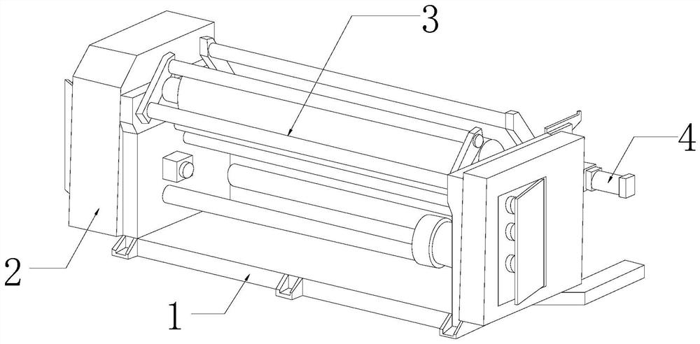
[0025] as attached figure 1 to attach Figure 5 Shown:

[0026] The invention provides a film cutting device, the structure of which includes a base 1, a body 2, a film frame 3, and a motor 4. The body 2 is respectively installed on the top of both ends of the base 1, and the film frame 3 is horizontally fixed on the body 2. Between, the motor 4 is installed on the back of the body 2.

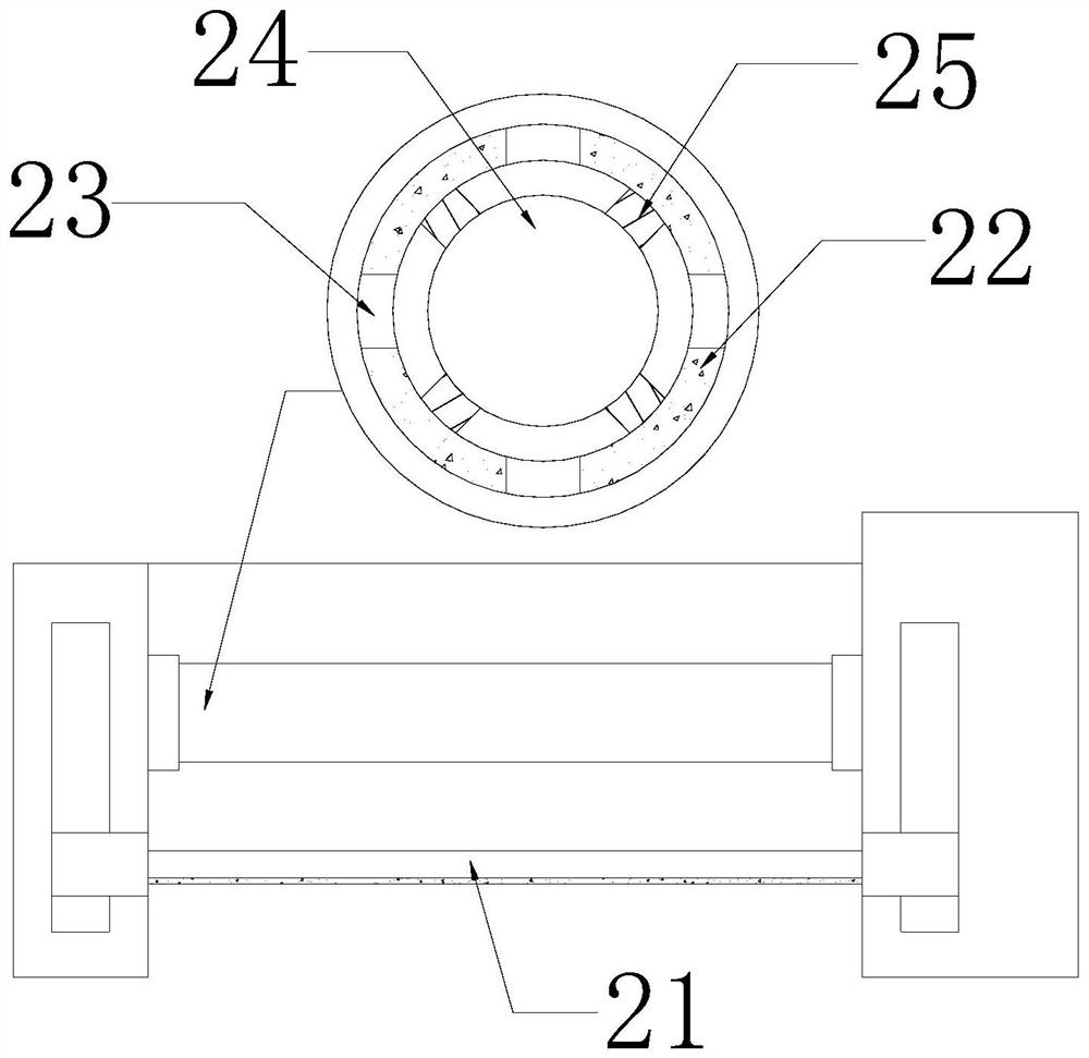
[0027] The body 2 is provided with a cutting knife 21, a rotating roller 22, an opening 23, a vibration mechanism 24, and a support block 25. The cutting knife 21 is installed at the bottom position between the bodies 2, and the rotating roller 22 is horizontally connected and installed on the Between the body 2 and above the cutting knife 21 , the opening 23 runs through between the outer wall and the inner wall of the rotating roller 22 , and the vibrating mechanism 24 is fixedly installed on the inner wall of the rotating roller 22 through a support block 25 .

[0028] Wherein, the vibrat...

Embodiment 2

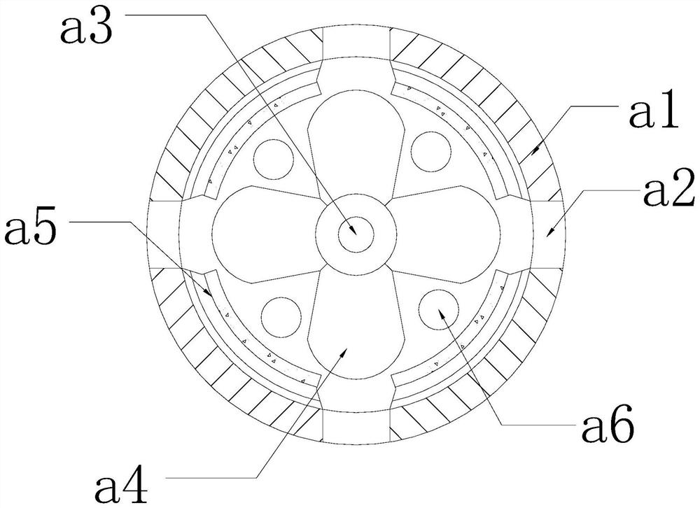
[0034] as attached Figure 6 to attach Figure 7 Shown:

[0035] Wherein, the opening 23 is provided with a stacking cavity r1, a clamping plate r2, a bearing r3, a clamping block r4, a pull bar r5, and a pushing block r6. The stacking cavity r1 is respectively arranged on the inner wall of the opening 23, and the clamping plate r2 r3 is connected and installed on the top of the stacking chamber r1, the block r4 is integrated with the outside of the bottom of the stacking chamber r1, the tie bar r5 is connected between the inner side of the clamping plate r2 and the inner wall of the stacking chamber r1, and the pushing block r6 It is arranged inside the storage chamber r1 and movably cooperates with the clamping plate r2. The storage chamber r1 is at an inclined angle, allowing liquid to flow in along the slope of the storage chamber r1 and reducing liquid backflow.

[0036] Wherein, the clamp r2 is provided with a plate body t1, a groove t2, an elastic strip t3, and a push b...


PUM


Abstract

The invention discloses film slitting equipment which structurally comprises a base, machine bodies, a film frame and a motor. The machine bodies are installed at the tops of the two ends of the base respectively; and the film frame is horizontally fixed between the machine bodies. Due to the fact that a nylon film absorbs moisture in air, the film is attached to the surface of a rotating roller; a pushing ball of a vibration mechanism moves in a supporting ring under the action of centrifugal force to impact a deformation block, so that airflow in the deformation block is discharged along an opening, a film attached to the outer wall of the rotating roller is separated from the rotating roller under the thrust of the airflow, the conveying speed of the rotating roller to the film is increased, cutting position dislocation is reduced, the sizes of the slit films are kept the same, and food can be normally packaged; and due to the fact that liquid in the films drips downwards under the extrusion force of the rotating roller, the liquid dripped from the films is collected through an accumulation cavity formed in the opening, so that liquid gathering on the outer wall of the rotating roller is reduced, friction force between the films and the rotating roller is reduced, and the film conveying speed is increased.

Description

technical field [0001] The invention belongs to the field of films, and more specifically relates to a film cutting device. Background technique [0002] Because nylon film has good oil resistance and heat resistance, it is widely used in packaging fried food. In order to facilitate food packaging, a slitter is used to cut the film into appropriate sizes according to the volume of the food. Nylon film is placed on the film frame of the cutting machine, and the rotating roller drives the film to be conveyed through the slitting knife for slitting; in the prior art, when the slitting machine is used to slit the nylon film, because the nylon film is easy to absorb moisture, when the moisture in the air When the content is large, the nylon film absorbs water molecules in the air, causing the film to stick to the surface of the rotating roller, and the friction coefficient increases, the conveying speed of the rotating roller to the film slows down, and the cutting position is pr...

Claims


Application Information

Patent Timeline
Patent Type & Authority Applications(China)
IPC IPC(8): B26D7/00B65H35/02B65H20/02
CPCB26D7/00B65H20/02B65H35/02
Inventor 余国钦
Owner 潘新凤
Why Eureka
Try Eureka