Oil-electric hybrid injection molding machine

An injection molding machine, oil-electric technology, applied in the field of oil-electric hybrid injection molding machine, can solve the problems of high injection molding cost, low utilization rate of servo motor, low utilization efficiency of motor, etc., and achieve the effect of convenient implementation and simple structure

Pending Publication Date: 2021-05-28
GIENKEE PLAS SCI & TECH SUZHOU
View PDF0 Cites 1 Cited by
  • Summary
  • Abstract
  • Description
  • Claims
  • Application Information

AI Technical Summary

Problems solved by technology

[0007] However, in most injection molding machines, the injection axis and the feeding axis are each controlled by a servo motor. The injection motor drives the ball screw to rotate through the injection belt, pushing the screw forward and backward; when feeding, the feeding motor drives the screw to rotate. Come on, injection and feeding each require a servo motor (generally, the injection servo motor is larger than the feeding servo motor), and during the entire injection process, they will not simultaneously produce the maximum torque to work (that is to say, when the output power of the injection motor is maximum, feeding The motor will not do the maximum output at the same time, and vice versa), so the utilization efficiency of the motor is relatively low. Therefore, not only the selection of the servo motor increases the cost of the injection molding machine, but also the low utilization rate of the servo motor results in high injection molding costs.

Method used


Image

  • Oil-electric hybrid injection molding machine
  • Oil-electric hybrid injection molding machine
  • Oil-electric hybrid injection molding machine

Examples


Embodiment 1

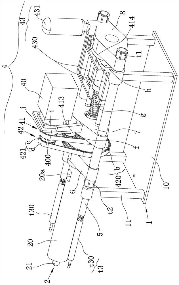
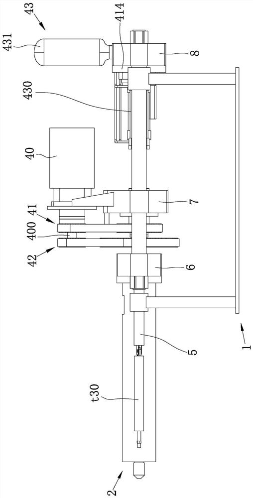
[0078] Such as figure 1 As shown, the oil-electric hybrid three-platen injection molding machine in this embodiment includes a machine base 1 , a barrel 2 , a screw 3 , and a power system 4 .

[0079] Specifically, the base 1 includes an injection platform 10 and a pillar 11 located on the injection platform 10, wherein the injection platform 10 is square, and there are four pillars 11, which are correspondingly distributed at the four corners of the injection platform 10. The power system 4 passes along the screw 3 Two injection tie rods 5 extending in the longitudinal direction are erected on the pillar 11.

[0080] In this example, the two injection rods 5 correspond to pass through the two pillars 11 on the same side.

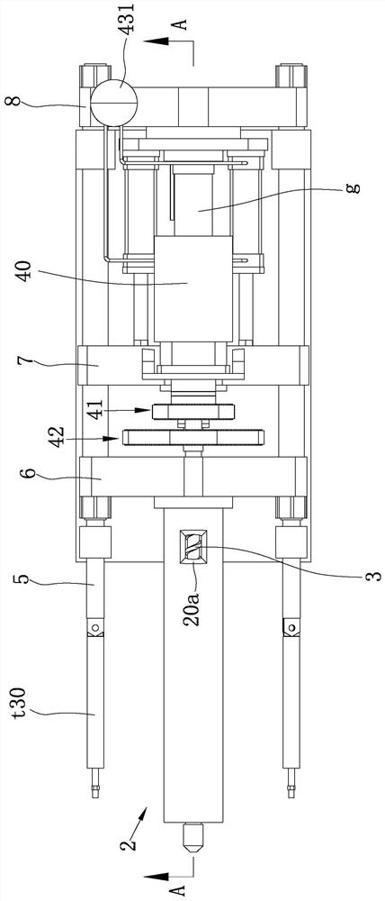
[0081] The barrel 2 includes a barrel body 20 with a cavity formed therein, and a nozzle 21 arranged at the front end of the barrel body 20, wherein the barrel body 20 is provided with a plastic raw material inlet 2a.

[0082] The screw 3 extends along th...

Embodiment 2

[0115] combine Figure 5 As shown, the basic structure and implementation principle of the hybrid two-platen injection molding machine in this embodiment are the same as those in Embodiment 1, except that in this example there are only the injection head plate 6 and the injection tail plate 8, and the power system There are also differences in the implementation of 4.

[0116] combine Image 6 As shown, the cylinder body 20 is fixed to the injection head plate 6 from the rear end, the injection tail plate 8 is slidably arranged on the machine base 1 as the screw 6 moves along its own length direction, and the power motor 40 and the feeding unit 42 are arranged on the injection On the tail plate 8 , the injection unit 41 and the auxiliary cylinder 430 are arranged on the injection head plate 6 and the injection tail plate 8 . With the setting of two boards, the installation of the power system is realized, the structure is compact, the volume is small, and it is easy to imple...


PUM


Abstract

The invention relates to an oil-electric hybrid injection molding machine which comprises a machine base, a charging barrel, a screw rod and a power system. The power system comprises a power motor, an ejection unit, a feeding unit and an oil pressure auxiliary unit, wherein the ejection unit comprises an ejection power part, an ejection transmission part and a first clutch; the feeding unit comprises a feeding power part, a feeding transmission part and a second clutch, and the first clutch and the second clutch are arranged apart on an output shaft; the oil pressure auxiliary unit comprises an auxiliary oil cylinder and an energy accumulator, and during ejection, the energy accumulator releases energy, and a rodless cavity of the auxiliary oil cylinder is filled with oil. On one hand, through cooperation of the double clutches which are coaxially arranged, the same motor can be used for injection and feeding, and the use specification of the motor is reduced; and on the other hand, by adoption of the auxiliary oil cylinder, under oil-electric hybrid condition, especially during ejection, the ejection pressure, speed and precision are ensured; and meanwhile, during post-loosening and backpressure actions, high-precision movement of the screw rod can be realized through oil pressure control.

Description

technical field [0001] The invention belongs to the field of injection molding machines, and in particular relates to an oil-electric hybrid injection molding machine. Background technique [0002] At present, the all-electric injection molding machine has the following working status: [0003] Injection: The injection motor drives the rotating screw to push the screw forward; [0004] Pressure holding: keep the pressure of the mold cavity and material tube constant for a period of time, and the injection motor continues to work at this time; [0005] Feeding: The feeding motor drives the screw to rotate (the screw can only rotate in one direction), and when the feeding motor drives the screw to rotate, the pressure at the front of the screw will increase and generate back pressure. At this time, the ball screw needs to move backward to release the back pressure. At this time, the feeding motor and the injection motor work at the same time; [0006] Back loosening (anti-c...

Claims


Application Information

Patent Timeline
Patent Type & Authority Applications(China)
IPC IPC(8): B29C45/50B29C45/76B29C45/17
CPCB29C45/5008B29C45/76B29C45/17B29C2045/1784
Inventor 陈明华
Owner GIENKEE PLAS SCI & TECH SUZHOU
Why Eureka
Try Eureka