Construction method of large-span reinforced concrete bridge

A construction method and long-span technology, applied in bridges, bridge parts, bridge construction, etc., can solve the problems of difficult quality control of steel girders, high cost, self-heaviness of long-span steel-concrete bridges, etc., to reduce the amount of steel used in design , avoiding the downward deflection of the steel beam, and improving the effect of mechanical performance

Pending Publication Date: 2021-05-28
CHINA FIRST HIGHWAY ENG +1
View PDF7 Cites 0 Cited by
  • Summary
  • Abstract
  • Description
  • Claims
  • Application Information

AI Technical Summary

Problems solved by technology

[0004] The technical problem to be solved by the present invention is that the existing long-span steel-concrete bridge has a large self-weight, which leads to difficult quality control and high cost of prefabricated steel beams. Construction method of tall long-span steel-concrete bridge

Method used


Image

  • Construction method of large-span reinforced concrete bridge
  • Construction method of large-span reinforced concrete bridge
  • Construction method of large-span reinforced concrete bridge

Examples


Embodiment Construction

[0030] The technical solutions of the present invention will be clearly and completely described below in conjunction with the accompanying drawings. Apparently, the described embodiments are some of the embodiments of the present invention, but not all of them. Based on the embodiments of the present invention, all other embodiments obtained by persons of ordinary skill in the art without making creative efforts belong to the protection scope of the present invention.

[0031] In the description of the present invention, it should be noted that the terms "center", "upper", "lower", "left", "right", "vertical", "horizontal", "inner", "outer" etc. The indicated orientation or positional relationship is based on the orientation or positional relationship shown in the drawings, and is only for the convenience of describing the present invention and simplifying the description, rather than indicating or implying that the referred device or element must have a specific orientation, ...


PUM


Abstract

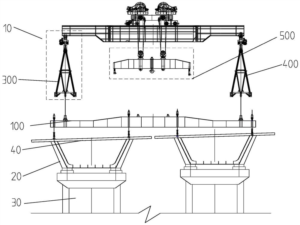
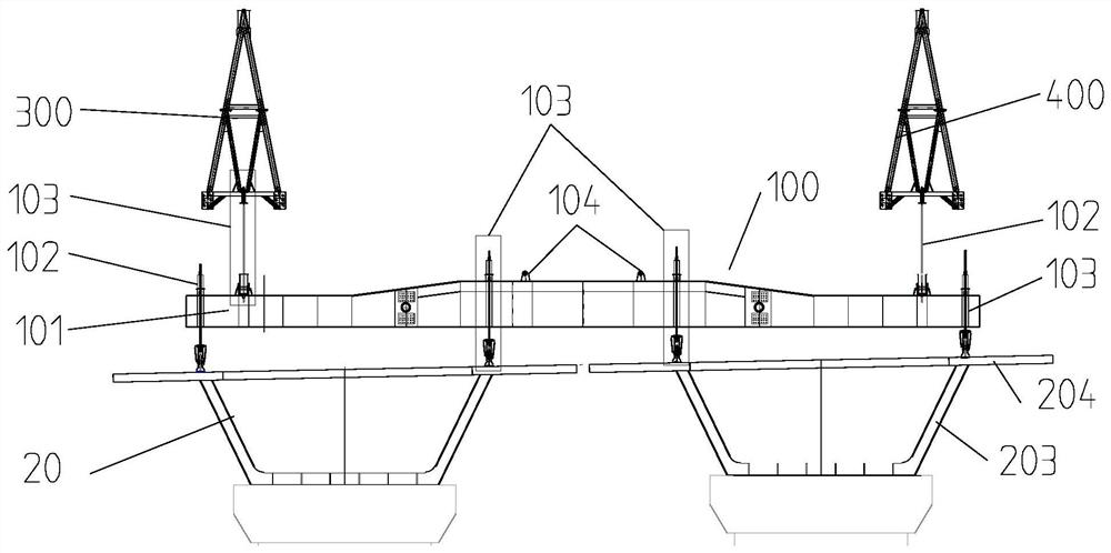
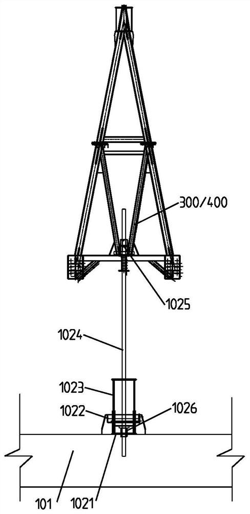
The invention discloses a construction method of a large-span reinforced concrete bridge. The method comprises the following steps: erecting a prefabricated steel beam between adjacent piers, and arranging at least one reverse lifting part on the prefabricated steel beam; mounting a reverse lifting hanging cross beam on a bridge girder erection machine, wherein at least one reverse lifting force applying part is arranged on the reverse lifting hanging cross beam; the reverse lifting force applying part is connected with the reverse lifting parts of the prefabricated steel beam, the reverse lifting force applying part is controlled to apply upward first reverse lifting force to the reverse lifting parts, and the prefabricated bridge deck slabs are sequentially laid on the prefabricated steel beam after the first reverse lifting force is applied; after the second reverse lifting force is applied, concrete is poured into joints between the adjacent prefabricated bridge deck slabs, and curing is conducted for set time; and the reverse lifting force applied to the reverse lifting parts by the reverse lifting force applying part is unloaded, the next steel beam is erected by the bridge girder erection machine, and the next steel beam is connected with the previous steel beam. The problems that due to the fact that an existing large-span steel-concrete bridge is large in dead weight, the quality control difficulty of the prefabricated steel beam is large, and the manufacturing cost is high are solved.

Description

technical field [0001] The invention relates to the field of bridge construction, in particular to a construction method for a long-span steel-concrete bridge. Background technique [0002] The bridge with reinforced concrete composite structure can exert the material characteristics of concrete under compression and steel plate under tension, and has the characteristics of light weight and superior seismic performance of the structure; in the current severe environmental protection situation, the use of steel structures can save concrete engineering and reduce ground material mining. It has good economic benefits and environmental protection significance, and has obvious industry competitiveness in the future transportation infrastructure industry. [0003] At present, when the long-span steel girders are erected by the bridge erecting machine, the main process is to use the bridge erecting machine to hoist the steel girders and then install the bridge deck, reproduce the w...

Claims


Application Information

Patent Timeline
IPC IPC(8): E01D21/00E01D19/12
CPCE01D21/00E01D19/125
Inventor 王成伟刘伟李可科王坤杰刘拯王涛赵永忠许涛吴效岺张劲松江财发武迎宾翟晓军杨纪硕
Owner CHINA FIRST HIGHWAY ENG
Why Eureka
Try Eureka