
Rodless cylinder

A rodless cylinder, cylinder block technology, applied in bearings, linear motion bearings, fluid pressure actuating devices, etc., can solve the problem of low running accuracy of rodless cylinders, small load capacity of rodless cylinders, and easy sliding of the slider from side to side. and other problems, to achieve the effect of large load capacity, long service life and stable operation

Pending Publication Date: 2021-05-28
能手模组技术(无锡)有限公司
View PDF0 Cites 0 Cited by
  • Summary
  • Abstract
  • Description
  • Claims
  • Application Information

AI Technical Summary

Problems solved by technology

The existing rodless cylinder is composed of a cylinder and a slide block that is movably connected to the upper part of the cylinder and can move axially along the cylinder body. Obviously, firstly, this structure makes the load force on the rodless cylinder be related to the load area of ​​the slide block and The bending strength of the slider is related. Because the load area of ​​the slider is small and the bending strength is weak, the load capacity of the rodless cylinder is small. The second is due to the lack of a mechanism to guide the operation of the slider, so when the slider is running It is easy to shake from side to side, making the operation unstable, resulting in low operation accuracy and short service life of the rodless cylinder

Method used


Image

  • Rodless cylinder
  • Rodless cylinder
  • Rodless cylinder

Examples


Embodiment Construction

[0024]The present invention will be further described below in conjunction with the accompanying drawings and specific examples to better understand the invention and can be implemented, but the embodiments are not limited thereto.

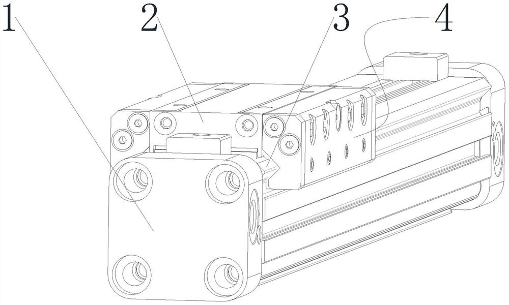
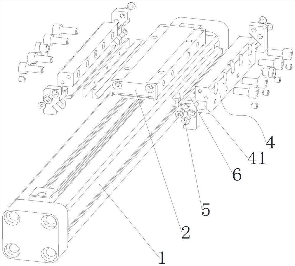
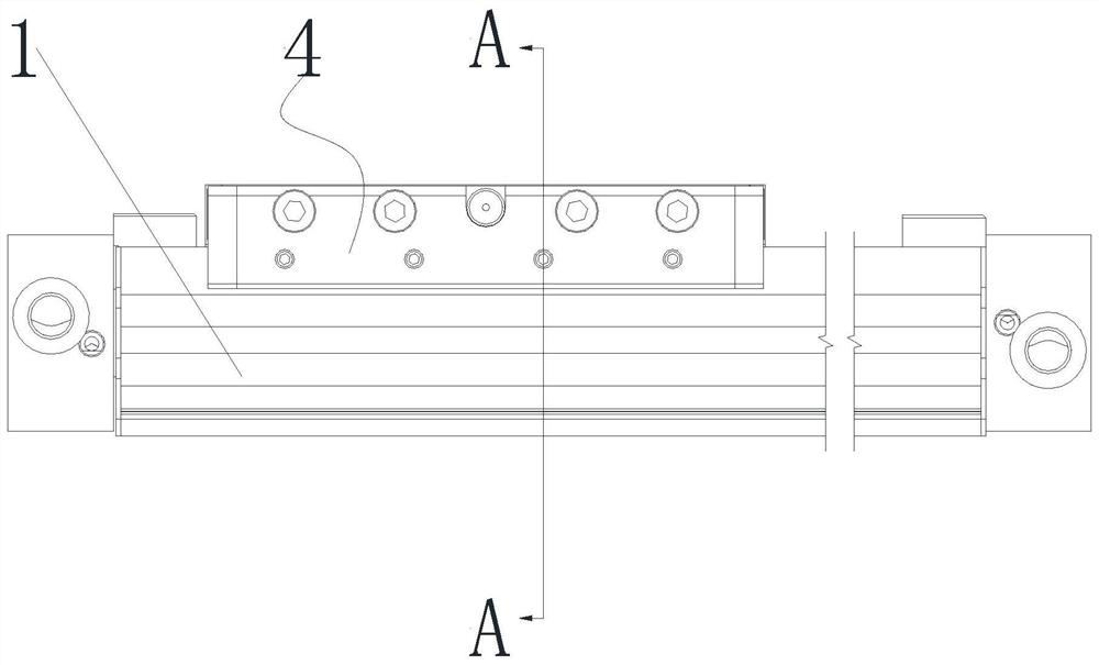
[0025]Referfigure 1 ,figure 2 ,image 3 withFigure 4As shown, a non-bar cylinder comprising a cylinder 1 and a movable slider 2 on the cylinder 1 and can move axially along the cylinder 1, the top surface of the slider 2 is horizontally, the side of the cylinder 1 A pair of symmetrical support ridges 3 on both sides of the slider 2 are provided on the top wall, in the present embodiment, the support ridge 3 is V-shaped. The guiding mounting blocks 4 are detachably connected to both sides of the slider 2, in the present embodiment, the slider 2 is threaded with the guide mounting block 4. The top surface of the mounting block 4 is flush with the top surface of the slider 2, and it is provided with a guide groove 41 that can accommodate the support ridge 3 on...


PUM


Abstract

The invention discloses a rodless air cylinder which comprises a cylinder body and a sliding block which is movably connected to the cylinder body and can move in the axial direction of the cylinder body, wherein the top surface of the sliding block is horizontal, a pair of supporting protruding strips symmetrically located on the two sides of the sliding block in the axial direction of the cylinder body is arranged on the side top wall of the cylinder body, guide mounting blocks are detachably connected to the two sides of the sliding block respectively, the top surfaces of the guide mounting blocks are flush with the top surface of the sliding block, guide grooves capable of containing supporting protruding strips are formed in the portions, opposite to the supporting protruding strips, of the guide installation blocks, and guide strips which are tightly attached to the supporting protruding strips all the time and matched with the supporting protruding strips are detachably connected into the guide grooves. The rodless cylinder solves the technical problems of how to effectively improve the loading capacity of the rodless cylinder and ensure the stable operation of the rodless cylinder, and has the advantages of large load, stable operation, high operation accuracy, long service life and the like.

Description

Technical field[0001]The present invention relates to the field of cylinders, in particular, referring to a rodless cylinder.Background technique[0002]The rodless cylinder is a driving device, since it has the advantages of light weight, simple structure, small space, and is therefore widely used in the mechanical field. The existing barrel cylinder is connected to the upper portion of the cylinder and the active slider that can be moved along the cylinder and movably moving along the cylinder. One is such a configuration such that the load capacity of the non-rod gas is subjected to the load area of ​​the slider and the load area of ​​the slider and The bending strength of the slider is related, since the load area of ​​the slider is small and the bending strength is weak, the load capacity of the rod cylinder is small, and the second is due to the lack of mechanisms for the operation of the slider, so the slider is operated. It is easy to shake, so that the operation is not smooth...

Claims


Application Information

Patent Timeline
Patent Type & Authority Applications(China)
IPC IPC(8): F16C29/00F16C29/02F15B15/14F15B15/20
CPCF15B15/1423F15B15/1428F16C29/005F16C29/02
Inventor 刘海冰龚耀峰
Owner 能手模组技术(无锡)有限公司
Learn More