Super Junction Power Devices

A power device, n-type technology, applied in the direction of semiconductor devices, electric solid devices, electrical components, etc., can solve the problem of long reverse recovery time, achieve fast reverse recovery speed, small chip size, and improve reverse recovery speed Effect

Active Publication Date: 2022-04-15
SUZHOU ORIENTAL SEMICONDUCTOR CO LTD
View PDF10 Cites 0 Cited by
  • Summary
  • Abstract
  • Description
  • Claims
  • Application Information

AI Technical Summary

Problems solved by technology

[0004] In view of this, the purpose of the present invention is to provide a super junction power device with fast reverse recovery speed to solve the long technology of reverse recovery time caused by the problem of minority carrier injection in super junction power devices in the prior art question

Method used


Image

  • Super Junction Power Devices
  • Super Junction Power Devices
  • Super Junction Power Devices

Examples


Embodiment Construction

[0020] The technical solutions of the present invention will be fully described below through specific implementation manners with reference to the drawings in the embodiments of the present invention. At the same time, in order to clearly illustrate the specific implementation methods of the present invention, the schematic diagrams listed in the drawings of the specification enlarge the size of the layers and regions described in the present invention, and the listed figures do not represent the actual size. The embodiments listed in the specification should not be limited to the specific shapes of the regions shown in the drawings of the specification, but include the resulting shapes such as deviations caused by manufacturing and the like.

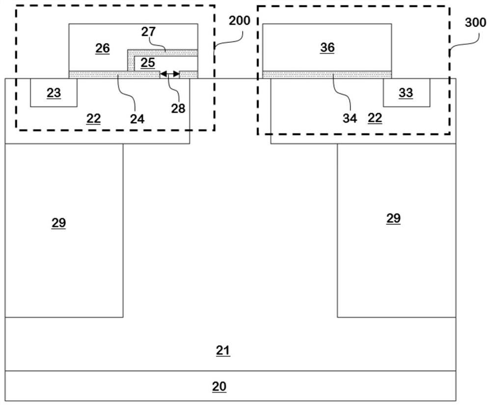
[0021] figure 2 It is a schematic cross-sectional structure diagram of the first embodiment of a super junction power device provided by the present invention, such as figure 2 As shown, a super junction power device provided by an ...


PUM


Abstract

A super-junction power device provided by an embodiment of the present invention includes at least one first MOSFET unit and at least one second MOSFET unit, the first MOSFET unit has different threshold voltages when the super-junction power device is turned on and off, and the super-junction When the power device conducts in the reverse direction, the reverse current can flow through the first MOSFET unit, which improves the reverse recovery speed of the super junction power device; the second MOSFET unit has a shorter current channel than the first MOSFET unit , can effectively control the chip size of the super junction power device. The super junction power device of the embodiment of the present invention has a small chip size while having a fast reverse recovery speed.

Description

technical field [0001] The invention belongs to the technical field of semiconductor super-junction power devices, in particular to a semiconductor super-junction power device with fast reverse recovery speed and small chip size. Background technique [0002] The cross-sectional structure of a semiconductor superjunction power device in the prior art is as follows: figure 1 As shown, it includes: an n-type drain region 50, the n-type drain region 50 is connected to the drain voltage through a drain contact metal layer 58; an n-type drift region 51 located on the n-type drain region 50 is located at the top of the n-type drift region 51 The p-type body region 52, the n-type source region 53 located in the p-type body region 52, the n-type source region 53 and the p-type body region 52 are connected to the source voltage through the source contact metal layer 57; located below the p-type body region The p-type columnar doped region 59; the current channel located in the p-typ...

Claims


Application Information

Patent Timeline
Patent Type & Authority Patents(China)
IPC IPC(8): H01L27/088H01L29/06H01L29/788
CPCH01L27/088H01L29/788H01L29/0649H01L29/0603H01L29/0634H01L29/06H01L29/78H01L27/07
Inventor 龚轶袁愿林刘伟刘磊毛振东
Owner SUZHOU ORIENTAL SEMICONDUCTOR CO LTD
Why Eureka
Try Eureka