Channel modeling method combining ray tracing method and finite difference time domain method

A finite difference in time domain and ray tracing technology, which is applied in transmission monitoring, special data processing applications, electrical components, etc., can solve problems such as the inability to accurately predict the radio wave transmission process, and achieve reduced system complexity, simple algorithms, and easy scenarios Effect

Inactive Publication Date: 2021-05-28
NORTHWESTERN POLYTECHNICAL UNIV
View PDF5 Cites 10 Cited by
  • Summary
  • Abstract
  • Description
  • Claims
  • Application Information

AI Technical Summary

Problems solved by technology

[0005] Aiming at the problems existing in the prior art, the present invention provides a channel modeling method combining ray tracing and finite difference time domain method to solve the problem that the existing deterministic modeling technology cannot accurately predict the radio wave transmission process in an electrically small-scale environment problems, and improved the media with complex structures encountered in the modeling process, and accurately predicted the field values ​​​​brought by phenomena such as scattering and diffraction

Method used


Image

  • Channel modeling method combining ray tracing method and finite difference time domain method
  • Channel modeling method combining ray tracing method and finite difference time domain method
  • Channel modeling method combining ray tracing method and finite difference time domain method

Examples


Embodiment Construction

[0045] In order to make the object, technical solution and advantages of the present invention more clear, the present invention will be further described in detail below in conjunction with the examples. It should be understood that the specific embodiments described here are only used to explain the present invention, not to limit the present invention.

[0046] The present invention provides a channel modeling method combining ray tracing and time-domain finite difference method. The present invention will be described in detail below in conjunction with the accompanying drawings.

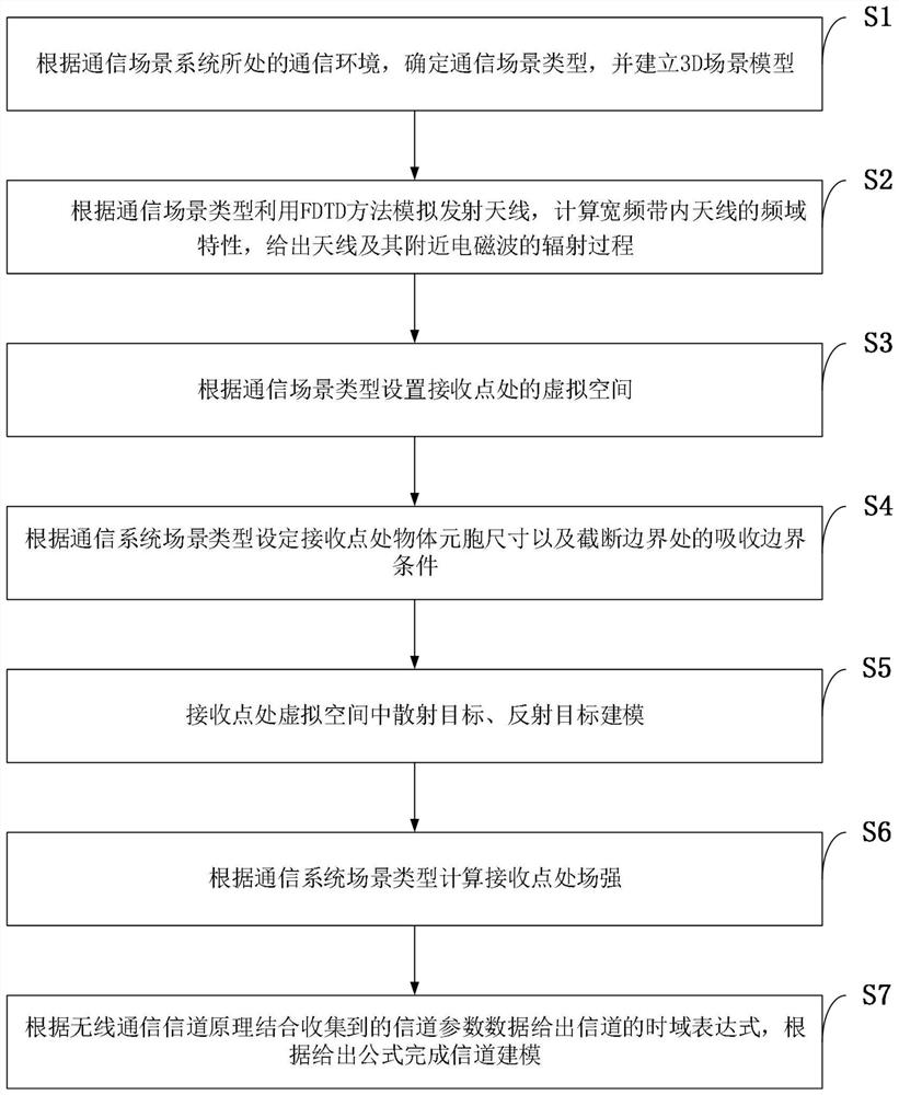
[0047] Such as figure 1 As shown, a channel modeling method combining ray tracing and finite difference time domain method provided by an embodiment of the present invention includes the following steps:

[0048] S1: According to the communication environment of the communication scene system, determine the type of communication scene, and establish a 3D scene model, mainly including the geome...


PUM


Abstract

The invention belongs to the technical field of radio frequency wireless communication, particularly relates to a channel modeling method combining ray tracing and a finite difference time domain method, adopts a channel modeling method based on ray tracing and FDTD (finite difference time domain method), and aims to solve the problems in the prior art. Various characteristic parameters in an electromagnetic wave propagation process are obtained by using a ray tracing technology, characteristic parameters such as amplitude, angle, phase and time delay can be obtained for each path so as to perform analysis and calculation, and in addition, simulation analysis is performed on an antenna and an electromagnetic wave radiation process close to the antenna at a transmitting end in combination with an FDTD method. And meanwhile, a virtual space is established at a receiving end to carry out modeling analysis on a receiving antenna and a scatterer, so that corresponding electromagnetic parameters are obtained. And finally, channel modeling is given according to channel parameters obtained in the ray propagation process.

Description

technical field [0001] The invention belongs to the technical field of radio frequency wireless communication, and in particular relates to a channel modeling method combining ray tracing and time domain finite difference method. Background technique [0002] Wireless signals usually arrive at the receiving end through a series of direct, reflection, diffraction, scattering or transmission methods from the transmitting end in a complex propagation environment, resulting in large-scale fading caused by path loss and shadow fading and caused by multipath Small-scale fading caused by the effect. In order to better evaluate the wireless communication system, it is necessary to model the wireless channel, that is, to summarize, abstract and simulate the channel in order to find the propagation law of electromagnetic waves in different typical scenarios. In consideration of R&D cost and R&D cycle, simulation is usually used for channel modeling. Among them, the representative te...

Claims


Application Information

Patent Timeline
Patent Type & Authority Applications(China)
IPC IPC(8): H04B17/00H04B17/391G06F30/20
CPCH04B17/0087H04B17/391G06F30/20
Inventor 蒋毅任书蝶张若南吴江
Owner NORTHWESTERN POLYTECHNICAL UNIV
Why Eureka
Try Eureka