
Drying device for centrifugal casting coating layer of cylinder jacket

A centrifugal casting and drying device technology, which is applied to casting molding equipment, manufacturing tools, metal processing equipment, etc., can solve the problems of low drying efficiency, fast heat conduction of coating layer, and short service life, so as to improve product quality and improve Drying efficiency, the effect of avoiding casting defects

Pending Publication Date: 2021-06-01
GKN ZHONGYUAN CYLINDER LINER CO LTD
View PDF0 Cites 0 Cited by
  • Summary
  • Abstract
  • Description
  • Claims
  • Application Information

AI Technical Summary

Problems solved by technology

[0002] In order to adapt to the production of higher explosive pressure cylinder liner materials, in the centrifugal casting process, it is necessary to spray a thicker coating layer on the inner wall of the centrifugal casting metal mold. The existing drying method of water-based coating is to rely on the waste heat of the metal mold to spray the coating into it. The layer is dried in one direction from the outer circle to the center of the inner hole, and the drying efficiency is low. Moreover, due to the thickening of the metal coating layer, it is difficult to fully dry the coating layer in the original method, which will lead to faster heat conduction of the coating layer. , the material of the cylinder liner is too cold, so that the metallographic phase of the blank casting of the cylinder liner is unqualified, or the casting structure is prone to shrinkage, shrinkage, low mechanical properties, poor safety factor, early wear, short service life and other defects, which seriously affect the cylinder set of product quality

Method used


Image

  • Drying device for centrifugal casting coating layer of cylinder jacket

Examples


Embodiment

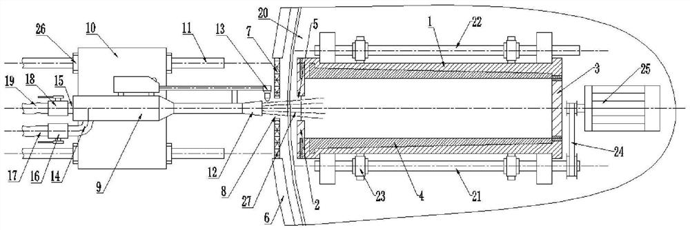
[0018] Such as figure 1 As shown, a cylinder liner centrifugal casting paint layer drying device includes a centrifugal casting machine and a metal mold 1 thereof, the front and rear ends of the metal mold are respectively provided with a front cover plate 2 and a rear bottom plate 3, and the metal mold The inner wall of the mold is sprayed with a paint layer 4, and the center of the front cover plate is provided with a sprue 5, and the protective cover 6 of the centrifugal casting machine in front of the sprue is provided with an observation window, and the observation window is equipped with a A protective net 7, a fire hole 8 is provided in the middle of the protective net, a fire spray gun 9 is arranged in front of the fire hole, and the fire spray gun is erected on a mobile trolley 10, and a track 11 is laid below the mobile trolley, Described mobile trolley can move along described track, and the rear portion of described fire spray gun is provided with fire spray nozzle...


PUM


Abstract

The invention belongs to the technical field of centrifugal casting, and particularly relates to a drying device for a centrifugal casting coating layer of a cylinder jacket. The drying device comprises a centrifugal casting machine and a metal mold thereof, a front cover plate and a rear bottom plate are arranged at the front end and the rear end of the metal mold respectively, a coating layer is sprayed on the inner wall of the metal mold, a sprue gate is formed in the center of the front cover plate, a flame gun is arranged in front of the sprue gate and erected on a moving trolley, a rail is laid below the moving trolley, the moving trolley can move along the rail, a flame nozzle is arranged on the rear portion, close to the flame penetrating hole, of the flame gun, an ignition gun is arranged on the side of the flame gun, a gas port and a combustion-supporting gas port are formed in the front portion of the flame gun, the gas port is connected with a first gas supply hose through a first gas inlet valve, and the combustion-supporting gas port is connected with a second gas supply hose through a second gas inlet valve. According to the drying device, natural gas is adopted for reverse drying from inside to outside from the metal mold, the coating layer is dried faster and more fully, and casting defects caused by supercooling of a cylinder jacket material are avoided.

Description

technical field [0001] The invention belongs to the technical field of centrifugal casting, in particular to a coating layer drying device for centrifugal casting of a cylinder liner. Background technique [0002] In order to adapt to the production of higher explosive pressure cylinder liner materials, in the centrifugal casting process, it is necessary to spray a thicker coating layer on the inner wall of the centrifugal casting metal mold. The existing drying method of water-based coating is to rely on the waste heat of the metal mold to spray the coating into it. The layer is dried in one direction from the outer circle to the center of the inner hole, and the drying efficiency is low. Moreover, due to the thickening of the metal coating layer, it is difficult to fully dry the coating layer in the original method, which will lead to faster heat conduction of the coating layer. , the material of the cylinder liner is too cold, so that the metallographic phase of the blank...

Claims


Application Information

Patent Timeline
Patent Type & Authority Applications(China)
IPC IPC(8): B22D13/10B22C23/02
CPCB22C23/02B22D13/10
Inventor 刘书胜汤晓虎聂治国璩森郝文虎刘春梅王艳玲杨忠武
Owner GKN ZHONGYUAN CYLINDER LINER CO LTD
Learn More