Numerical control drilling machine tool
A machine tool and fan technology, applied in the field of CNC drilling machine tools, can solve the problems of adsorption on the inner wall of the shell, difficult to clean, difficult to collect, etc.
- Summary
- Abstract
- Description
- Claims
- Application Information
AI Technical Summary
Problems solved by technology
Method used
Image


Examples
Embodiment 1
[0027] as attached figure 1 to attach Figure 4 Shown:
[0028] The invention discloses a numerically controlled drilling machine tool, the structure of which is provided with a control panel 1, an electric box 2, a knife lock seat 3, a main shaft 4, a casing 5, a base 6, and a protective door 7, and the control panel 1 and the electric box 2 are energized connection, the knife lock seat 3 is movably connected inside the casing 5, the rear end of the control panel 1 is fixedly connected to the front surface of the casing 5, the bottom of the casing 5 is detachably installed above the base 6, and the protective door 7 is movably connected On the inner wall of the shell 5 , the front end of the electrical box 2 is detachably mounted on the rear end of the shell 5 .
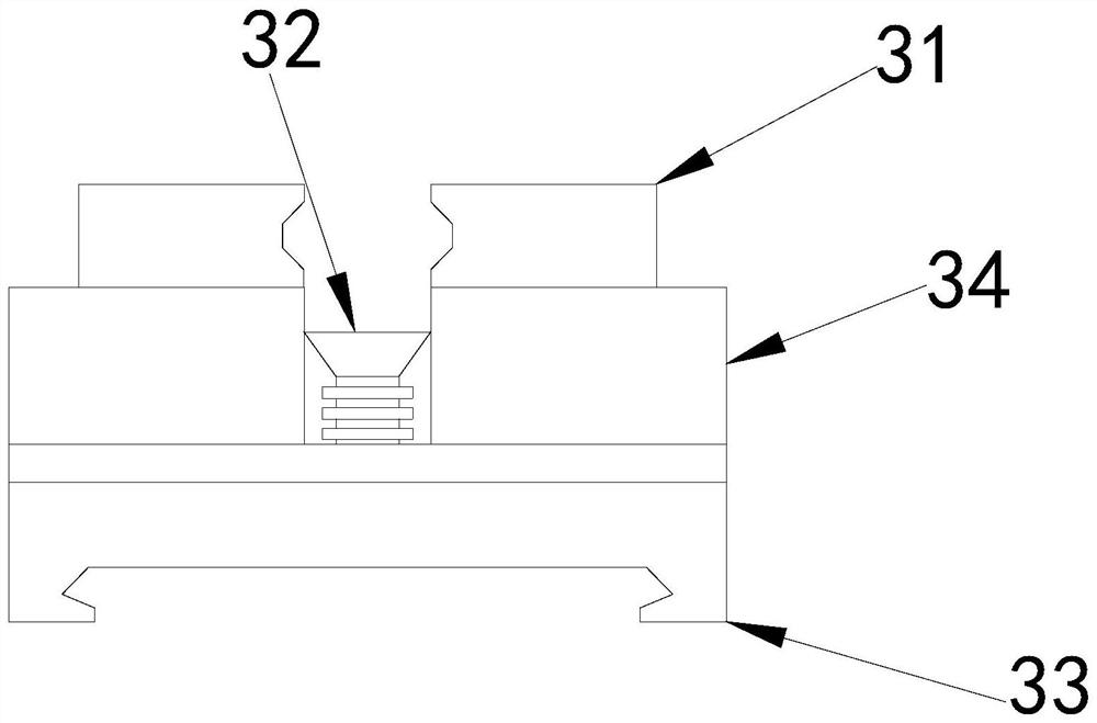
[0029] Wherein, the lock knife seat 3 is provided with a splint 31, a collection device 32, a bottom block 33, and an upper limit block 34, the bottom of the splint 31 is movably connected inside the upper limit ...
Embodiment 2
[0035] as attached Figure 5 to attach Figure 7 Shown:
[0036] The invention discloses a numerically controlled drilling machine tool. The crushing tube 325 is provided with a limit bearing B1, a crushing rod B2, a tube wall B3, and an acceleration device B4. The limit bearing B1 is fixedly connected above the inner wall of the tube wall B3. The crushing rod B2 is movably connected between the limit bearing B1 and the acceleration device B4. The top of the acceleration device B4 is detachably installed on the pipe wall B3. The crushing rod B2 stands between the pipe walls B3 and is in the shape of a screw, which can be easily Driven by fan 322.
[0037]Wherein, the acceleration device B4 includes a ball bearing B41, a connecting rod B42, a base B43, a magnetic ring B44, and a magnetic block B45. The ball bearing B41 is movably connected to the outer wall of the connecting rod B42. The lower end of the outer wall of B42 is movably connected, the magnetic ring B44 is matche...
PUM
 Abstract
Description
Claims
Application Information
PatSnap Eureka turns technology decisions into work you can execute. Powered by our Innovation Knowledge Graph, it runs expert workflows across engineering, life sciences, materials and intellectual property. Get your review-ready output in minutes.


