Automatic assembling equipment for mini electromagnetic valve

An automatic assembly and solenoid valve technology, applied in metal processing equipment, assembly machines, manufacturing tools, etc., can solve the problems of high assembly cost and low degree of automatic assembly automation, and achieve the goal of reducing investment, improving work efficiency and reducing economic expenses. Effect

Inactive Publication Date: 2021-06-01
孙莉新
View PDF1 Cites 3 Cited by
  • Summary
  • Abstract
  • Description
  • Claims
  • Application Information

AI Technical Summary

Problems solved by technology

[0005] The present invention aims at the above-mentioned defects existing in the prior art, and proposes an automatic assembly equipment for mini solenoid valves, which solves the problems of low automatic assembly automation and high assembly cost of existing solenoid valves

Method used


Image

  • Automatic assembling equipment for mini electromagnetic valve
  • Automatic assembling equipment for mini electromagnetic valve
  • Automatic assembling equipment for mini electromagnetic valve

Examples


Embodiment 1

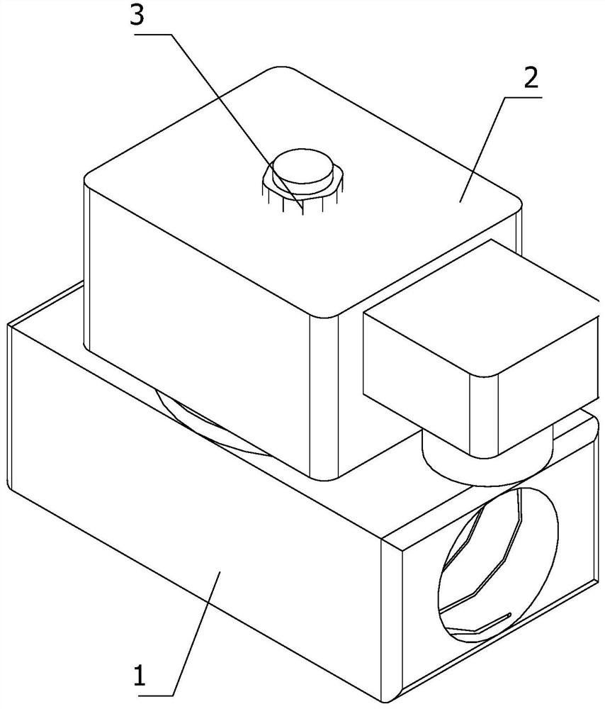
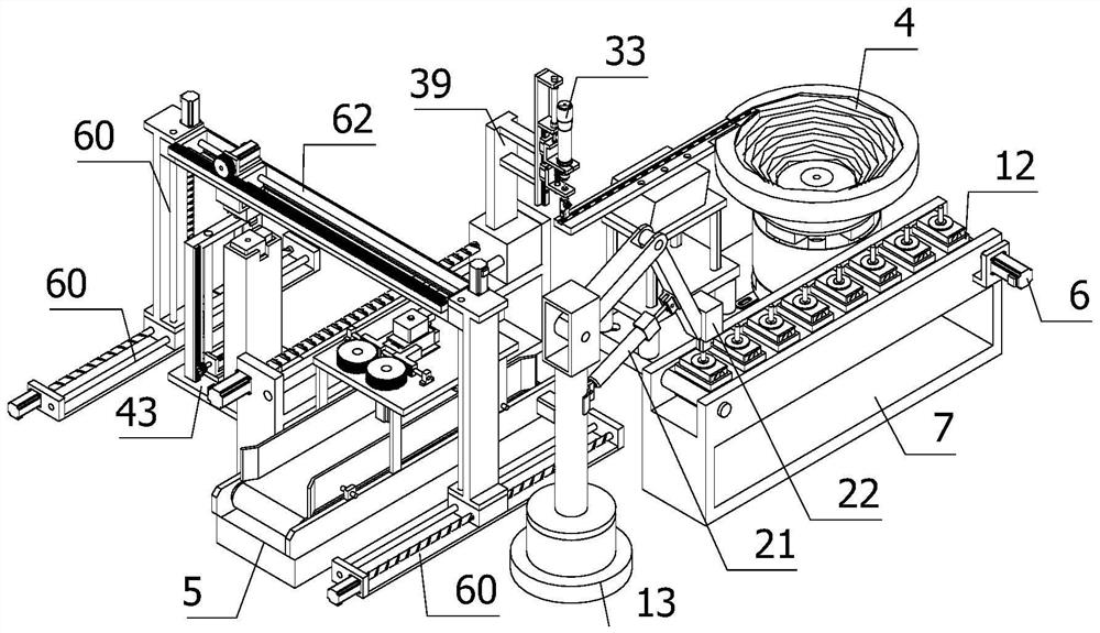
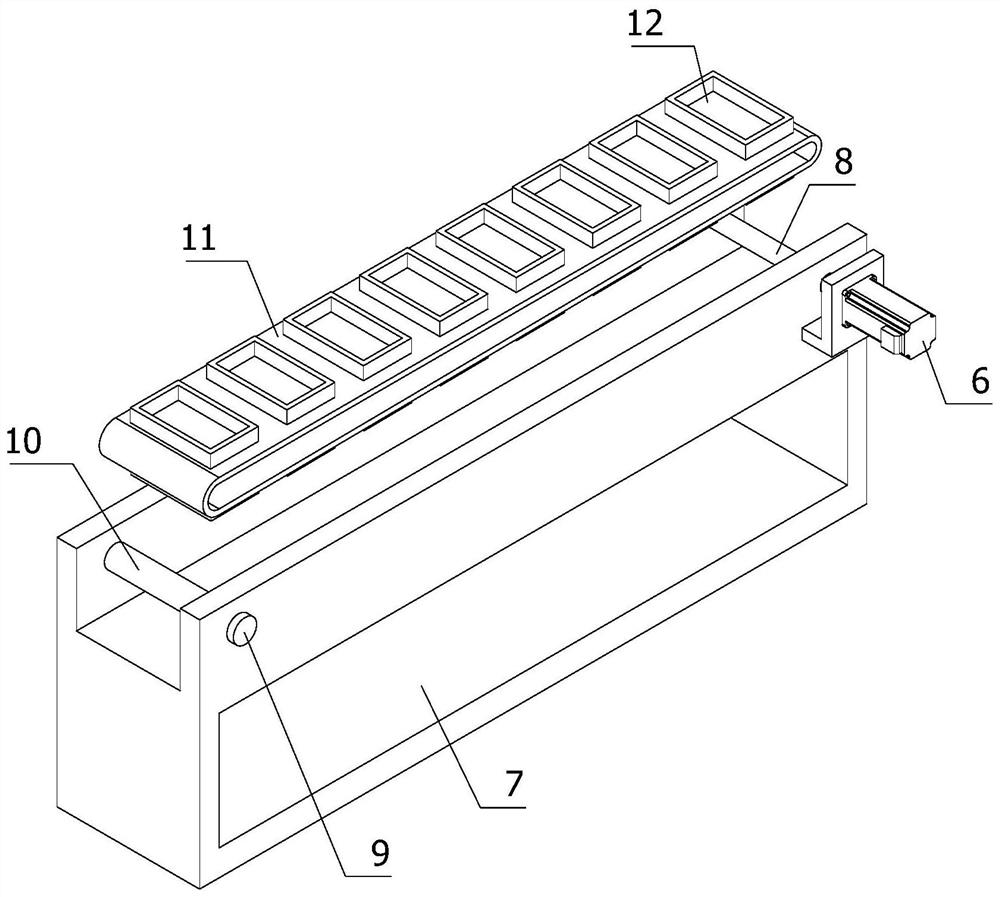
[0040] refer to Figure 1 to Figure 11 As shown, an automatic assembly equipment for a mini solenoid valve, including a feeding mechanism, a rotary clamping mechanism, a first assembly assembly, a second assembly assembly, a lifting mechanism and a blanking assembly; first place the valve seat 1 on the loading assembly , the loading assembly transports the valve seat 1 to the rotary clamping mechanism, and then the rotary clamping mechanism transports the valve seat 1 to the unloading assembly, and then the lifting mechanism moves the valve body 2 upwards. At the same time, the second assembly assembly Move to the top of the lifting mechanism, grab the valve body 2 and move it to the valve seat 1 at the blanking assembly, put the valve body 2 into the valve seat 1, and then the first assembly component transports the nut 3 to the blanking assembly, and put the nut 3. Screw together with the valve seat 1 and the valve body 2. After screwing, transport the assembled mini solenoi...

Embodiment 2

[0056] Compared with Embodiment 1, in this embodiment, the stabilizing mechanism includes a fixed frame 48, a fifth motor 49, a cross bar 50, a fixed rod 51, two fourth gears 52, two extrusion blocks 53 and two shaft seats 54, the fixed frame 48 is vertically arranged on the top of the conveyor belt 5, the top of the fixed frame 48 is provided with a rectangular groove 55 and two protrusions 56, and the two shaft seats 54 are spaced apart and arranged parallel to each other on the fixed frame 48 The two ends of a protrusion on the top, the two ends of the cross bar 50 are connected with two shaft seats 54, the two extruding blocks 53 are sleeved on the two ends of the cross bar 50, and the ends of the two extruding blocks 53 away from the protrusion are arranged There are tooth marks 57, a fourth gear is arranged on the top of the fixed frame 48 near one end of the extrusion block that has the tooth marks 57, and the other fourth gear is arranged on the top of the fixed frame 4...


PUM


Abstract

The invention relates to the field of electromagnetic valve assembling, in particular to automatic assembling equipment for a mini electromagnetic valve. The automatic assembling equipment comprises a feeding mechanism, a rotary clamping mechanism, a first assembling component, a second assembling component, a lifting mechanism and a discharging component; the rotary clamping mechanism is vertically arranged at the tail end of the output direction of the feeding mechanism; the first assembling assembly comprises a vibration disc, a screwing mechanism and a translation mechanism; the discharging assembly comprises a stabilizing mechanism, a material conveying belt and an opening and closing mechanism; and the second assembling assembly comprises a grabbing mechanism and a linkage mechanism. Through tight combination of the first assembling assembly and the second assembling assembly, automatic assembling of parts of the electromagnetic valve is achieved, and the labor input is reduced; a valve seat is rapidly conveyed to a machining platform through the arrangement of the feeding mechanism and the rotary clamping mechanism, and a valve body is moved to the second assembly to be grabbed out through the lifting mechanism; and through the automatic operation process, the economic expenditure of an enterprise is reduced, the economic benefits are increased, the working benefits are improved, and the development of the enterprise is promoted.

Description

technical field [0001] The invention relates to the field of solenoid valve assembly, in particular to automatic assembly equipment for miniature solenoid valves. Background technique [0002] Solenoid valve is an industrial equipment controlled by electromagnetic. It is an automatic basic component used to control fluid. It belongs to actuator and is not limited to hydraulic and pneumatic. It is used to adjust the direction, flow, speed and other parameters of the medium in the industrial control system. Solenoid valves can cooperate with different circuits to achieve the expected control, and the control accuracy and flexibility can be guaranteed. There are many kinds of solenoid valves. Different solenoid valves play a role in different positions of the control system. The most commonly used ones are check valves, safety valves, directional control valves, and speed regulating valves. [0003] For example, in the automatic assembly device for solenoid valve moving iron ...

Claims


Application Information

Patent Timeline
Patent Type & Authority Applications(China)
IPC IPC(8): B23P21/00
CPCB23P21/004
Inventor 孙莉新
Owner 孙莉新
Why Eureka
Try Eureka