Bubble removing machine for rectangular film-covered paper box

A film-coating and carton technology, applied in papermaking, paper/cardboard containers, container manufacturing machinery, etc., can solve problems such as cardboard sagging, incomplete lamination of film, structural deformation, etc.

Inactive Publication Date: 2021-06-01
陈克华
View PDF0 Cites 1 Cited by
  • Summary
  • Abstract
  • Description
  • Claims
  • Application Information

AI Technical Summary

Problems solved by technology

[0003] Aiming at the deficiencies of the prior art, the present invention provides a rectangular film-coated carton foaming machine, which solves the problem of the softness of the cardboard material of the carton when the joint between the film and the carton is squeezed. When extrusion, the cardboard will be deformed due to extrusion, causing the cardboard to sag, and the film cannot be completely attached to the surface of the cardboard, so that the carton can not be covered.

Method used


Image

  • Bubble removing machine for rectangular film-covered paper box
  • Bubble removing machine for rectangular film-covered paper box
  • Bubble removing machine for rectangular film-covered paper box

Examples


Embodiment 1

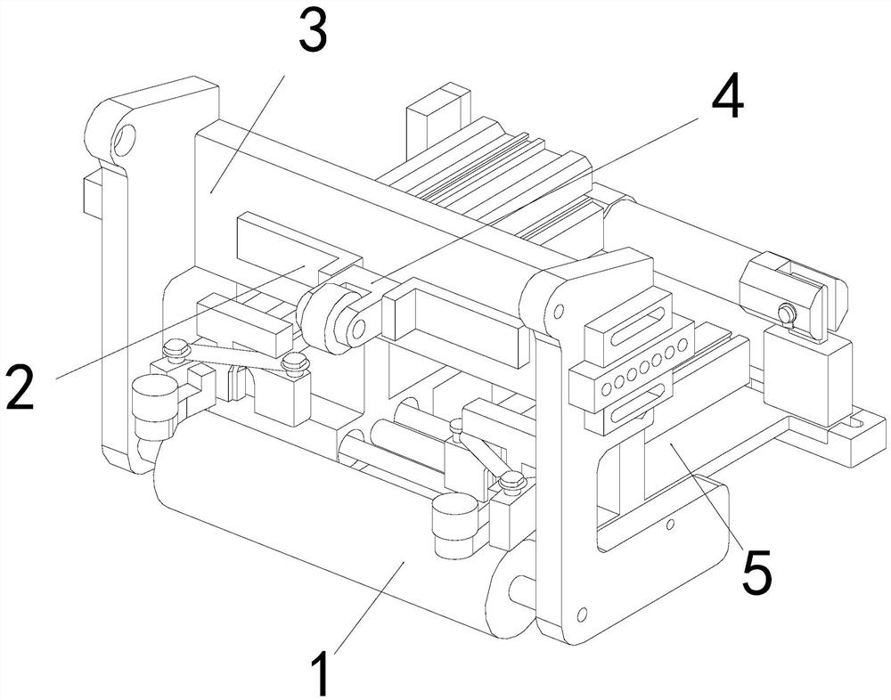
[0025] as attached figure 1 to attach Figure 4 As shown, the present invention provides a rectangular film-coated carton debubbling machine, its structure includes a film-coated roller 1, an assembly plate 2, a main body frame 3, a defoamer 4, a support seat 5, and the two ends of the film-coated roller 1 The outer wall is nested and fitted on the inner walls on both sides below the front end of the main frame 3, the rear end of the assembly plate 2 is fixed above the front end of the main frame 3 by screws, and the rear end of the main frame 3 is embedded and fixed on the front end of the support seat 5. Both sides of the rear end of the bubbler 4 are movably engaged between the assembly plates 2. There are two assembly plates 2 arranged opposite to the two ends of the defoamer 4. By assembling the two ends in parallel, the defoamer is prevented from 4 Offset during work;

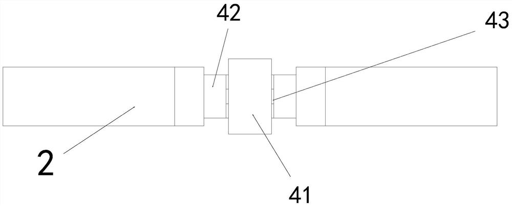
[0026] The defoamer 4 is composed of a foam rolling roller 41, an assembly seat 42, and a connecting...

Embodiment 2

[0031] as attached Figure 5 to attach Figure 7 As shown: the booster b1 is composed of a fixed end plate c1, a connecting plate c2, a lifting plate c3, and a reactivator c4. The lower end of the fixed end plate c1 is welded and fixed to the inner wall of the outer ring b4, and the connecting plate The outer wall of the lower end of c2 is embedded and fixed on the upper end of the fixed end plate c1, the lower two ends of the lifting plate c3 are movably matched with the upper ends of the connecting card plate c2, the reactivator c4 is assembled on the inner wall of the connecting card plate c2, and the connecting card After the plate c2 is combined with the lifting plate c3, its structure is a ring structure, which can be averaged to the whole, so as to avoid the distortion of the structure caused by excessive force on a single point.

[0032]Wherein, the reactivator c4 is composed of the outer plate d1, the connecting bar d2, the nesting shaft d3, the clamping shaft d4, th...


PUM


Abstract

The invention provides a bubble removing machine for a rectangular film-covered paper box. The bubble removing machine structurally comprises a film covering roll, an assembly plate, a main body frame, a bubble remover and a supporting base. The outer walls of the two ends of the film covering roll are assembled on the inner walls of the two sides of the lower portion of the front end of the main body frame in a nested mode, and the rear end of the assembly plate is fixed to the upper portion of the front end of the main body frame through screws. When the bubble removing machine is used, a film is bonded to the film covering roll and attached to the surface of a carton needing film covering through the film covering roll, and the film covering roll carries the film and flatly lays the film on the surface of the carton through pushing of equipment. After attachment is completed, the bubble remover at the rear end can roll the attached film. During downward pressing, the bubble removing roll can move upwards due to counter-acting force, a rolling ring is supported through a booster arranged in the bubble removing roll in the moving process, and the rolling ring is better attached to the surface of the carton. The situation is avoided that as the structure of the carton is changed after the carton is stressed, the rolling ring cannot be completely attached to the surface of the carton, and air at the joint of the film and the carton cannot be completely exhausted.

Description

technical field [0001] The invention relates to the field of film-coating equipment for cartons, and more specifically, relates to a bubble-removing machine for rectangular film-coated cartons. Background technique [0002] Lamination, also known as "overplastic", "film", etc., refers to the use of transparent plastic film to cover the surface of the printed matter. After the previous processing of the carton is completed, the surface of the carton must be covered. The characteristics of the attached film are used to improve the water resistance and heat resistance of the carton after the lamination is completed, making the structure of the carton stronger than that of the uncoated carton and improving the aesthetics of the carton. When the equipment covers the carton, it will squeeze the film while covering the film, so that the film can be more attached to the surface of the carton, and the air at the joint between the film and the carton will be discharged by extrusion. ...

Claims


Application Information

Patent Timeline
Patent Type & Authority Applications(China)
IPC IPC(8): B31B50/74B31B110/35B31B120/00B32B37/00B32B37/10B65H37/04
CPCB32B37/003B32B37/10B32B2038/0052B65H37/04B31B50/74B31B2110/35B31B2120/00
Inventor 陈克华
Owner 陈克华
Why Eureka
Try Eureka