
New energy automobile charging pile with good heat dissipation function

A technology for new energy vehicles and charging piles, applied in electric vehicle charging technology, charging stations, electric vehicles, etc., can solve problems such as damage, poor heat dissipation, difficult air convection, etc., to achieve comprehensive and uniform heat dissipation and good cooling effect Effect

Active Publication Date: 2021-06-01
ZHEJIANG IND POLYTECHNIC COLLEGE
View PDF5 Cites 0 Cited by
  • Summary
  • Abstract
  • Description
  • Claims
  • Application Information

AI Technical Summary

Problems solved by technology

[0002] The new energy vehicle charging pile is similar to the fuel dispenser in the gas station. It can be fixed on the ground or the wall, and can charge various types of new energy vehicles according to different voltage levels. Although the existing charging pile has cooling holes, the heat dissipation The effect is not good, mainly because the charging pile is airtight, because it needs to be waterproof and dustproof to prevent short circuit of electronic equipment and signal disorder. Accelerate the aging of the circuit boards, cables and controllers in the charging pile, and cause damage in severe cases

Method used


Image

  • New energy automobile charging pile with good heat dissipation function
  • New energy automobile charging pile with good heat dissipation function
  • New energy automobile charging pile with good heat dissipation function

Examples


Embodiment Construction

[0027] In order to enable those skilled in the art to better understand the solutions of the present invention, the technical solutions in the embodiments of the present invention will be clearly and completely described below in conjunction with the drawings in the embodiments of the present invention. Obviously, the described embodiments are only It is a part of embodiments of the present invention, but not all embodiments. Based on the embodiments of the present invention, all other embodiments obtained by persons of ordinary skill in the art without making creative efforts shall fall within the protection scope of the present invention.

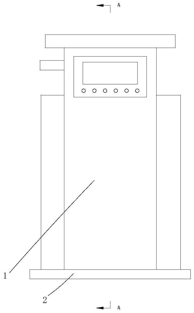
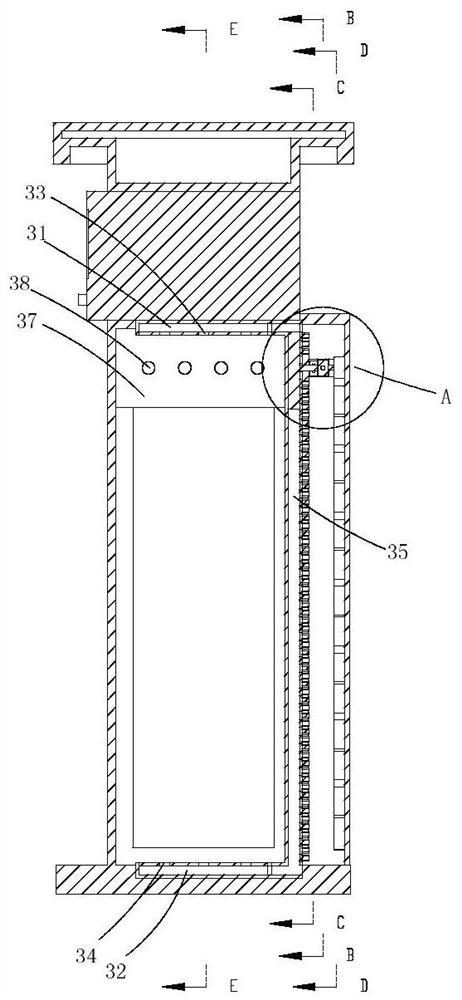
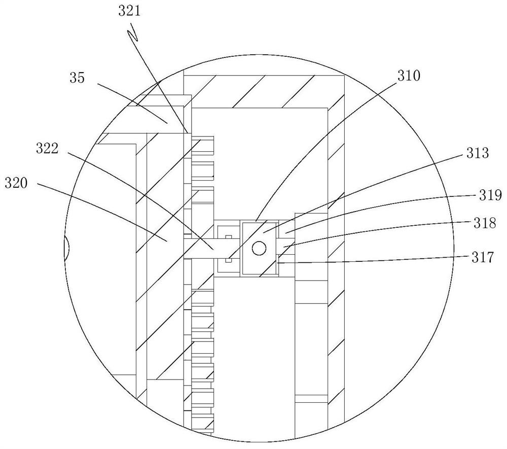
[0028] Such as Figure 1-17 As shown, a new energy vehicle charging pile with good heat dissipation function includes a charging pile body 1, a base 2 fixed at the bottom of the charging pile body, a cooling device inside the charging pile body, and a filtering device inside the cooling device. The cooling device includes an upper cavity...


PUM


Abstract

The invention discloses a new energy automobile charging pile with a good heat dissipation function. The new energy automobile charging pile comprises a charging pile body, a base fixedly arranged at the bottom end of the charging pile body, a cooling device arranged in the charging pile body and a filtering device arranged in the cooling device. The cooling device comprises an upper cavity, a lower cavity, a plurality of first through holes, a plurality of second through holes, a first channel, an air blowing cavity, an air suction cavity, a plurality of third through holes and a second channel, wherein the upper cavity and the lower cavity are fixedly arranged on the charging pile body, the first through holes are formed in the upper cavity in an equidistant array manner, the second through holes are formed in the lower cavity in an equidistant array manner, the air blowing cavity is movably formed in the side wall of the charging pile body, the air suction cavity is movably formed in the side wall of the charging pile body, the third through holes are formed in the air suction cavity at equal intervals, the refrigerating element is fixedly arranged in the air suction cavity, and the two ends of the second channel are fixedly arranged on the air suction cavity and the air blowing cavity correspondingly and used for communicating the air suction cavity and the air blowing cavity.

Description

technical field [0001] The invention relates to the technical field of new energy vehicles, in particular to a new energy vehicle charging pile with good heat dissipation function. Background technique [0002] The new energy vehicle charging pile is similar to the fuel dispenser in the gas station. It can be fixed on the ground or the wall, and can charge various types of new energy vehicles according to different voltage levels. Although the existing charging pile has cooling holes, the heat dissipation The effect is not good, mainly because the charging pile is airtight, because it needs to be waterproof and dustproof to prevent short circuit of electronic equipment and signal disorder. Accelerate the aging of the circuit boards, cables and controllers in the charging pile, and cause damage in severe cases. Contents of the invention [0003] In order to overcome the deficiencies of the prior art, the present invention provides a new energy vehicle charging pile with go...

Claims


Application Information

Patent Timeline
IPC IPC(8): B60L53/302B60L53/31
CPCB60L53/302B60L53/31Y02T10/70Y02T10/7072Y02T90/12
Inventor 李小红王建伟
Owner ZHEJIANG IND POLYTECHNIC COLLEGE
Learn More