Supercharge Your Innovation With Domain-Expert AI Agents!

Vacuum pumping and nitrogen filling mechanism in rotary type vacuum nitrogen filling machine

A vacuum and rotary technology, applied in the direction of pressurization/gasification packaging, etc., can solve the problems of low nitrogen utilization rate, high residual oxygen content of potato chip tubes, large nitrogen gas consumption, etc., to achieve convenient use and maintenance, Enhanced anti-oxidation effect and high nitrogen utilization efficiency

Pending Publication Date: 2021-06-01
JIANGSU JINRONG MACHINERY
View PDF0 Cites 0 Cited by
  • Summary
  • Abstract
  • Description
  • Claims
  • Application Information

AI Technical Summary

Problems solved by technology

Although the gas-filled chamber can achieve the purpose of filling nitrogen, it still has the following disadvantages: (1) The structure of the gas-filled chamber is complex and the price is high. The nitrogen gas in the gas-filled chamber is continuously open during use, and there is no targeted filling of nitrogen gas, resulting in nitrogen consumption. Large gas volume and low nitrogen utilization rate increase the cost of use of the enterprise; (2) The residual oxygen in the filled potato chip tube is high, thus reducing the anti-oxidation effect on sealed foods such as potato chips

Method used


Image

  • Vacuum pumping and nitrogen filling mechanism in rotary type vacuum nitrogen filling machine
  • Vacuum pumping and nitrogen filling mechanism in rotary type vacuum nitrogen filling machine
  • Vacuum pumping and nitrogen filling mechanism in rotary type vacuum nitrogen filling machine

Examples


Embodiment Construction

[0017] In order to make the object, technical solution and advantages of the present invention clearer, the present invention will be further described in detail below in conjunction with the accompanying drawings and embodiments. It should be understood that the specific embodiments described here are only used to explain the present invention, not to limit the present invention.

[0018] In describing the present invention, it is to be understood that the terms, "vertical", "upper", "lower", "front", "rear", "left", "right", "top", "bottom" , "inner", "outer" and other indicated orientations or positional relationships are based on the orientations or positional relationships shown in the drawings, which are only for the convenience of describing the present invention and simplifying the description, rather than indicating or implying that the referred devices or elements must Having a specific orientation, and specific orientation configuration and operation, should not be ...


PUM


Abstract

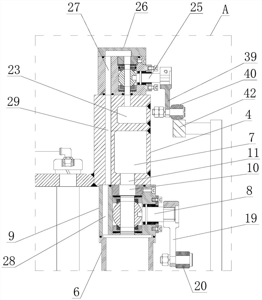
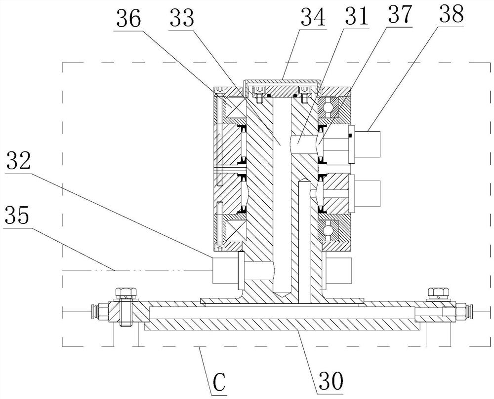
The invention discloses a vacuum pumping and nitrogen filling mechanism in a rotary type vacuum nitrogen filling machine. The vacuum pumping and nitrogen filling mechanism comprises a ring base, wherein a vacuum cavity is arranged in the ring base; each sealing sleeve communicates with the vacuum cavity through a vacuum pumping passage with a vacuum valve, the vacuum valve is controlled by a vacuum valve drive mechanism, a hollow vacuum tube is movably supported in a main shaft; a first rotating joint is arranged at the lower end of the vacuum tube, and the upper end of the vacuum tube communicates with the vacuum cavity; a nitrogen gas cavity is formed in the ring base, each sealing sleeve communicates with the nitrogen gas cavity through a nitrogen charging channel with a nitrogen charging valve, the nitrogen charging valve is controlled by a nitrogen charging valve drive mechanism, a connecting base is fixed to the top of the main shaft, and a nitrogen inlet, a nitrogen outlet and a nitrogen inlet channel in communication with the nitrogen inlet and the nitrogen outlet are formed in the connecting base; a second rotating joint capable of communicating the nitrogen inlet with a nitrogen charging machine is sleeved outside the connecting base; and the nitrogen outlet communicates with a nitrogen cavity inlet in the side wall of the ring base through a nitrogen connecting tube. The vacuum pumping and nitrogen filling mechanism has the advantages of high nitrogen charging efficiency, a high nitrogen utilization rate and low nitrogen consumption.

Description

technical field [0001] The invention relates to the technical field of food nitrogen filling equipment, in particular to a vacuum pumping and nitrogen filling mechanism in a rotary vacuum nitrogen filling machine. Background technique [0002] Potato chips are a very popular snack food at present, and they are generally packed in cylindrical cans. In the production process of potato chips packaging, before the potato chip tubes that have been put into the potato chips are sealed, it is generally necessary to fill the potato chip tubes with nitrogen and other protective gases to ensure the storage quality of sealed foods such as potato chips. At present, an air-filled chamber is generally used to fill the potato chip tube with nitrogen. The air-filled room is a relatively airtight space. The inflatable chamber is filled with nitrogen in a non-targeted manner. Although the gas-filled chamber can achieve the purpose of filling nitrogen, it still has the following disadvantage...

Claims


Application Information

Patent Timeline
IPC IPC(8): B65B31/04
CPCB65B31/04
Inventor 金荣陈阳平
Owner JIANGSU JINRONG MACHINERY
Features
  • R&D
  • Intellectual Property
  • Life Sciences
  • Materials
  • Tech Scout
  • Unparalleled Data Quality
  • Higher Quality Content
  • 60% Fewer Hallucinations
Learn More