Municipal solid waste drying device

A technology of municipal solid waste and drying equipment, applied in the field of municipal solid waste drying equipment, can solve the problems of increasing air humidity, affecting boilers, consumption, etc., and achieve the effect of reducing water vapor and improving drying effect

Inactive Publication Date: 2021-06-01
HARBIN UNIV OF SCI & TECH
View PDF5 Cites 0 Cited by
  • Summary
  • Abstract
  • Description
  • Claims
  • Application Information

AI Technical Summary

Problems solved by technology

Since municipal solid waste itself contains a certain amount of water, which is higher than that of coal, it will consume part of the heat during incineration, so it will reduce the heat utilization rate of municipal solid waste, and will affect the incineration of boilers to a certain extent, reducing the efficiency of boilers. Thermal efficiency increases operating costs, so it is necessary to dry municipal solid waste before incineration to improve the incineration efficiency of municipal solid waste
[0003] The commonly used drying method is natural air drying, drying and then stirring, which can only dry the surface layer of municipal solid waste, and the inner part of municipal solid waste needs to be dried by repeated pouring, which increases manpower and material resources and is inefficient, and the drying effect is poor and pollutes the environment , and when the ventilation pipe is used to penetrate the material, if the material is moved, the pipe needs to be re-arranged, resulting in waste of resources. During the drying process, water vapor is often directly discharged into the air to increase the air humidity, and at the same time make the material in contact with the air Humidity increases, which affects the drying effect and pollutes the environment. Therefore, developing a municipal solid waste drying device and solving the above problems is the direction that those skilled in the art need to study

Method used


Image

  • Municipal solid waste drying device
  • Municipal solid waste drying device
  • Municipal solid waste drying device

Examples


Embodiment Construction

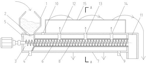
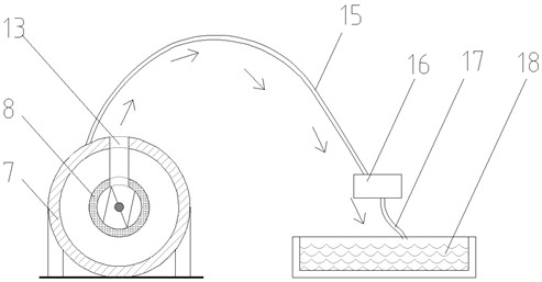
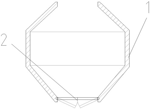
[0014] The present invention provides a drying device for municipal solid waste, the specific structure of which is as follows: Figures 1~3 As shown, it includes feeding port 1, throttle baffle 2, heating chamber 3, primary air inlet 4, primary air outlet 5, screw feeder 6, drying outer wall 7, drying inner wall 8, secondary air inlet 9 , secondary air outlet 10, collecting bucket 11, water vapor discharge port one 12, water vapor discharge port two 13, water vapor discharge port three 14, arc deflector 15, filter 16, overflow hose 17, Collection tank 18.

[0015] The throttling baffle 2 is provided at the bottom of the feed port 1, the primary air inlet 4 is provided at the bottom of the heating chamber 3, and the side of the heating chamber 3 away from the drying cylinder is provided with a primary air outlet 5; the drying outer wall 7 is provided with the drying inner wall 8 coaxially; the bottom of the end of the drying outer wall 7 away from the feed port 1 is provided ...


PUM


Abstract

The invention relates to a municipal solid waste drying device which is composed of a feeding port, a throttling baffle, a heating cavity, a drying chamber outer wall, a drying chamber inner wall, a water vapor discharging port, an arc-shaped flow guide plate, a filter and a liquid collecting box. Municipal solid waste enters the heating cavity through the feeding port, is subjected to primary hot air drying in the heating cavity, enters the drying chamber inner wall under the pushing action of a screw feeder, and is subjected to secondary drying with hot air on the outer side of the drying chamber inner wall. The dried municipal solid waste falls into a material collecting barrel. The water vapor discharging port is formed in the upper portion of the drying chamber inner wall, water vapor after drying is condensed and then falls into the filter through the arc-shaped guide plate, and filtered municipal solid waste water finally flows into the liquid collecting box. The municipal solid waste drying device can improve the drying effect, reduce water vapor discharged into the air effectively, recycle water in the municipal solid waste, and avoid the situation that the water vapor is directly discharged into the air to affect the drying effect. The municipal solid waste drying device has certain prospects in the future industry.

Description

technical field [0001] The invention belongs to the field of municipal solid waste drying, in particular to a municipal solid waste drying device. Background technique [0002] MSW has the advantages of sufficient sources and high volatile content. Incineration is an important way to solve the harmless treatment of MSW. Before incineration, MSW must be screened, transported, and dried. Since the municipal solid waste itself contains a certain amount of water, which is higher than that of coal, it will consume part of the heat during incineration, so it will reduce the heat utilization rate of the municipal solid waste, and will affect the incineration of the boiler to a certain extent. Therefore, it is necessary to dry the municipal solid waste before incineration to improve the incineration efficiency of municipal solid waste. [0003] The commonly used drying method is natural air drying, drying and stirring, which can only dry the surface layer of municipal solid waste. ...

Claims


Application Information

Patent Timeline
IPC IPC(8): F26B17/20F26B21/08F26B25/04
CPCF26B17/20F26B21/001F26B21/004F26B21/08F26B25/04
Inventor 吕薇万馨瞳李雪松王乾梁禹淇王旭
Owner HARBIN UNIV OF SCI & TECH
Why Eureka
Try Eureka