
Display chip test equipment

A display chip and testing equipment technology, applied in electronic circuit testing, automated testing systems, electrical measurement, etc., can solve the problems of high testing cost and low testing efficiency, and achieve the effect of improving testing efficiency and quality

Pending Publication Date: 2021-06-01
南京芯视元电子有限公司
View PDF0 Cites 1 Cited by
  • Summary
  • Abstract
  • Description
  • Claims
  • Application Information

AI Technical Summary

Problems solved by technology

[0003] The purpose of the present invention is to provide a display chip testing device for the above-mentioned deficiencies in the prior art, so as to improve the existing problems of high test cost and relatively low test efficiency when testing the packaged LcoS display chip

Method used


Image

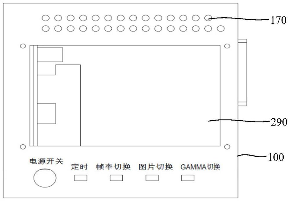
  • Display chip test equipment
  • Display chip test equipment
  • Display chip test equipment

Examples


Embodiment approach

[0034] Option One:

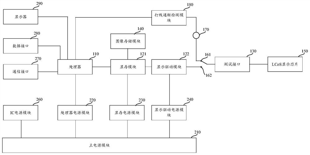
[0035] FPGA+DDR programming design can be selected. Since the source is 1080P image data, the output image data frame rate after FPGA processing needs to be as high as 360Hz to meet the LCoS display chip 150 display test requirements. The selected FPGA and DDR must meet the high-speed requirements. Receive the standard RGB data stream from the source through the FPGA algorithm, store it in the DDR according to a certain data format, and the DDR acts as a data cache, and then output the data stream in a specific format to the LCoS display chip 150 for display through the FPGA, and the output image data Compared with the source, the frame rate is increased, and the image color information is converted into sequential color, and at the same time, the FPGA can be controlled to output display images with different frame rates through key operations.

[0036] Time-sequential color refers to separating the RGB three-color bits of the image pixel into R, G, and B ...


PUM


Abstract

The invention provides display chip test equipment, and relates to the technical field of display chip testing. The display chip test equipment is characterized in that a processor is electrically connected with a display card module, the display card module is electrically connected with an image storage module, and a test interface connected with the display card module is also arranged on a circuit board; during test, the packaged display chip can be inserted into the test interface on the shell, so that the display card module can call data information pre-stored in the image storage module, then the display card module drives the packaged display chip to display corresponding images, verification of display characteristics of the packaged display chip is completed, and whether the packaged display chip is qualified or not is judged; therefore, the normal display characteristic of the packaged display chip after leaving the factory is ensured, and the quality of the product when leaving the factory is improved; and meanwhile, when the display characteristic of the packaged display chip is tested through the display chip test equipment, automatic testing can be carried out through cooperation of the processor, the display card module and the like and a testing program, and therefore, the testing efficiency can be improved.

Description

technical field [0001] The invention relates to the technical field of display chip testing, in particular to a display chip testing device. Background technique [0002] After the wire-bonded packaging of the LCoS display chip is completed, the electrical characteristics first need to be systematically tested. At present, the electrical characteristics test method for the packaged LCoS display chip is relatively traditional, and it is necessary to manually test the continuity of the wire bonding, power supply open and short circuit, and power consumption step by step. And other indicators, it is also necessary to manually record the test data. At the same time, in view of the application scenario of the packaged LCoS display chip, a preliminary test of its display effect is required. In view of the particularity of the packaged LCoS display chip, more test equipment is needed when testing its display characteristics, which makes the test cost higher and the test efficiency...

Claims


Application Information

Patent Timeline
Patent Type & Authority Applications(China)
IPC IPC(8): G01R31/28G01R1/04
CPCG01R1/0408G01R31/282G01R31/2834G01R31/2837G01R31/2843
Inventor 陈弈星吴庆飞
Owner 南京芯视元电子有限公司
Learn More