Optical imaging lens and imaging equipment

A technology of optical imaging lens and imaging surface, which is applied in the field of imaging lens, can solve the problems of high cost, small aperture, and large number of lenses, and achieve the effect of low cost and meeting the needs of use

Active Publication Date: 2021-06-01
JIANGXI LIANYI OPTICS CO LTD
View PDF12 Cites 1 Cited by
  • Summary
  • Abstract
  • Description
  • Claims
  • Application Information

AI Technical Summary

Problems solved by technology

[0003] At present, most of the surveillance lenses popular in the market have relatively small apertures, and most of the F# are above 2.0, resulting in poor imaging effects and low resolution of such lenses in strong light and low-light environments, and cannot meet complex indoor and outdoor conditions. Day and night high-definition imaging needs under ambient light; there are many surveillance lenses with a large number of lenses, and even use all-glass lenses, which makes the cost of the lens high and the size is large, which is not conducive to the promotion and application in the market

Method used


Image

  • Optical imaging lens and imaging equipment
  • Optical imaging lens and imaging equipment
  • Optical imaging lens and imaging equipment

Examples


no. 1 example

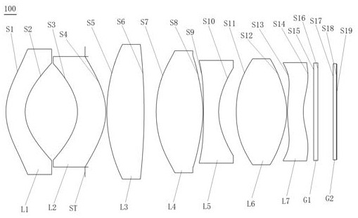
[0084] see figure 1 , which is a schematic structural view of the optical imaging lens 100 provided in the first embodiment of the present application. The optical imaging lens 100 includes a first lens L1, a second lens L2, a diaphragm ST, The third lens L3, the fourth lens L4, the fifth lens L5, the sixth lens L6, the seventh lens L7, the filter G1 and the cover glass G2.

[0085] Wherein, the first lens L1 has negative refractive power, the object side S1 of the first lens is a convex surface, and the image side S2 of the first lens is a concave surface;

[0086] The second lens L2 has negative refractive power, the object side S3 of the second lens is concave, and the image side S4 of the second lens is convex;

[0087] The third lens L3 has a positive refractive power, and both the object side S5 and the image side S6 of the third lens are convex;

[0088] The fourth lens L4 has a positive refractive power, and both the object side S7 and the image side S8 of the fourth...

no. 2 example

[0101] Such as Figure 8 As shown, it is a schematic diagram of the structure of the optical imaging lens 200 provided in this embodiment. The optical imaging lens 200 of this embodiment is substantially the same as that of the above-mentioned first embodiment, and the difference mainly lies in different design parameters.

[0102] Specifically, the design parameters of the optical imaging lens 200 provided in this embodiment are shown in Table 3.

[0103] table 3

[0104]

[0105] In this embodiment, the aspheric parameters of each lens in the optical imaging lens 200 are shown in Table 4.

[0106] Table 4

[0107]

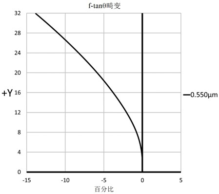
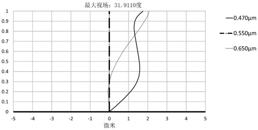
[0108] Please refer to Figure 9 , Figure 10 with Figure 11 , which show the f-tanθ distortion curve, the vertical axis chromatic aberration curve, and the modulation transfer function (MTF) curve of the optical imaging lens 200 respectively, from Figure 9 It can be seen that the optical distortion is controlled within -15%, indicating that the dis...

no. 3 example

[0110] Such as Figure 12 As shown, it is a schematic diagram of the structure of the optical imaging lens 300 provided in this embodiment. The optical imaging lens 300 of this embodiment is substantially the same as that of the above-mentioned first embodiment, and the difference mainly lies in different design parameters.

[0111] Specifically, the design parameters of the optical imaging lens 300 provided in this embodiment are shown in Table 5.

[0112] table 5

[0113]

[0114] In this embodiment, the aspheric parameters of each lens in the optical imaging lens 300 are shown in Table 6.

[0115] Table 6

[0116]

[0117] Please refer to Figure 13 , Figure 14 with Figure 15 , which show the f-tanθ distortion curve, the vertical axis chromatic aberration curve, and the modulation transfer function (MTF) curve of the optical imaging lens 300 respectively, from Figure 13 It can be seen that the optical distortion is controlled within -12.5%, indicating that th...


PUM


Abstract

The invention discloses an optical imaging lens and imaging equipment, and the optical imaging lens sequentially comprises a first lens with negative focal power, wherein the object side surface of the first lens is a convex surface, and the image side surface of the first lens is a concave surface; a second lens having negative focal power, whereinthe object side surface of the second lens is a concave surface, and the image side surface of the second lens is a convex surface; a diaphragm; a third lens having positive focal power, wherein the object side surface of the third lens is a convex surface, and the image side surface of the third lens is a convex surface; a fourth lens having positive focal power, wherein the object side surface of the fourth lens is a convex surface, and the image side surface of the fourth lens is a convex surface; a fifth lens having negative focal power,wherein the object side surface of the fifth lens is a concave surface, and the image side surface of the fifth lens is a concave surface; a sixth lens having positive focal power, wherein the object side surface of the sixth lens is a convex surface, and the image side surface of the sixth lens is a convex surface; and a seventh lens having negative focal power, wherein the object side surface of the seventh lens is a convex surface at a paraxial region and has an inflection point, and the image side surface of the seventh lens is a concave surface at a paraxial region and has an inflection point. The optical imaging lens has the advantages of ultra-large aperture, long focus and telephoto, high pixel, miniaturization, good thermal stability and the like.

Description

technical field [0001] The invention relates to the technical field of imaging lenses, in particular to a super large aperture telephoto optical imaging lens and imaging equipment. Background technique [0002] With the gradual expansion of the application range and scenarios of security monitoring video technology, and the increasing requirements for high-definition, networking, and intelligence of security monitoring, security monitoring lens products have high-definition image output, super large aperture, day and night confocal imaging, The technical level requirements for high reliability and other aspects are also increasing day by day. [0003] At present, most of the surveillance lenses popular in the market have relatively small apertures, and most of the F# are above 2.0, resulting in poor imaging effects and low resolution of such lenses in strong light and low-light environments, and cannot meet complex indoor and outdoor conditions. Day and night high-definitio...

Claims


Application Information

Patent Timeline
Patent Type & Authority Applications(China)
IPC IPC(8): G02B13/00G02B13/18G02B1/00
CPCG02B1/00G02B13/0015G02B13/0045
Inventor 章彬炜曾昊杰刘绪明曾吉勇
Owner JIANGXI LIANYI OPTICS CO LTD
Why Eureka
Try Eureka